|
数据搜索系统,热门电子元器件搜索 |
|
|
数据搜索系统,热门电子元器件搜索 |
|
FT-ROUTER5000 数据表(PDF) 2 Page - List of Unclassifed Manufacturers |
|
|
|||||||||||||||||||||||||||||
FT-ROUTER5000 数据表(HTML) 2 Page - List of Unclassifed Manufacturers |
|
|
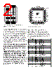
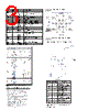
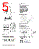
2 / 6 page  A FT Router 5000 IC based LONWORKS half router consists of the FT Router 5000 IC, the FT-X3 communications transformer, a crystal to generate the clock and an external serial memory to hold the router table. Two such half routers are used to build a full router. A half router design that uses FT Router 5000 can be used with a half router that uses the Router 5000 and an external transceiver such as RS-485, TP-1250, TP-78, FTT- 10A or LPT-11 to implement a LONWORKS full router. The FT Router 5000 IC can also be used to implement the FT section of a FTPL router along with the PL 3150 Smart Transceiver to implement the PL section. Additionally, the FT Router 5000 IC offers higher reliability since two half routers of a full router are logically isolated and a failure in one half router will not affect the other side’s network. LONWORKS application programs do not have to be modified to work with routers. Only the network configuration of a device has to be modified when a device is moved to the far side of a router. The required modifications to the network configuration can be done automatically by an installation tool. Routers are also independent of the network variables and message tags in a system, and can forward an unlimited number of them, which saves development cost because no code development is required to use routers in a system. It also saves installation and maintenance costs because router configuration is automatically managed by network server tools based on OpenLNS. Monitoring and control applications, such as those based on the LCA Object Server OCX, do not require modifications to work with multi-channel networks when routers are used. All network configuration is performed over the installed network, further minimizing installation and maintenance costs because routers do not have to be physically accessed to change their configuration. Figure 1: Block Diagram of the LONWORKS Router based on the FT Router 5000 Figure 2: FT Router 5000 Chip Pinout Table 1: FT Router 5000 Chip Pin Assignments Below is a table of the pin assignments for the FT Router 5000 chip. All digital inputs are low-voltage transistor- transistor logic (LVTTL) compatible, 5 V tolerant, with low leakage. All digital inputs are low-voltage transistortransistor logic (LVTTL) compatible, low leakage, 5V-tolerant. All digital outputs are slew-rate limited to reduce Electromagnetic Interference (EMI). Name Pin Number Type Description SVC~ 1 Digital I/O Service (active low) IO0 2 Digital I/O IO0 (side A to side B) IO1 3 Digital I/O IO1 (side A to side B) IO2 4 Digital I/O IO2 (side A to side B) IO3 5 Digital I/O IO3 (side A to side B) VDD1V8 6 Power 1.8 V Power Input (from internal voltage regulator) IO4 7 Digital I/O IO4 (side A to side B) VDD3V3 8 Power 3.3 V Power IO5 9 Digital I/O IO5 (side A to side B) IO6 10 Digital I/O IO6 (side A to side B) IO7 11 Digital I/O IO7 (side A to side B) IO8 12 Digital I/O IO8 (side A to side B) IO9 13 Digital I/O IO9 (side A to side B) IO10 14 Digital I/O IO10 (side A to side B) IO11 15 Digital I/O IO11 (not used for routers) VDD1V8 16 Power 1.8 V Power Input (from internal voltage regulator) TRST~ 17 Digital Input JTAG Test Reset (active low) VDD3V3 18 Power 3.3 V Power TCK 19 Digital Input JTAG Test Clock TMS 20 Digital Input JTAG Test Mode Select TDI 21 Digital Input JTAG Test Data In TDO 22 Digital Output JTAG Test Data Out XIN 23 Oscillator In Crystal oscillator input XOUT 24 Oscillator Out Crystal oscillator output VDDPLL 25 Power 1.8 V Power Input (from internal voltage regulator) GNDPLL 26 Power Ground VOUT1V8 27 Power 1.8 V Power Output (of internal voltage regulator) RST~ 28 Digital I/O Reset (active low) VIN3V3 29 Power 3.3 V Power Input VDD3V3 30 Power 3.3 V Power AVDD3V3 31 Power 3.3 V Power NETN 32 Comm Network Port (polarity insensitive) AGND 33 Ground Ground NETP 34 Comm Network Port (polarity insensitive) FT 5000 Smart Transceiver 1 2 3 4 5 6 7 8 9 10 11 12 36 35 34 33 32 31 30 29 28 27 26 25 GND NC NETP AGND NETN AVDD3V3 VDD3V3 VIN3V3 RST~ VOUT1V8 GNDPLL VDDPLL GND PAD Dashed line represents Pad (pin 49) Pad must be connected to GND SVC~ IO0 IO1 IO2 IO3 VDD1V8 IO4 VDD3V3 IO5 IO6 IO7 IO8 FT Router 5000 FT Router 5000 FT Router 5000 |
|
|
链接网址 |
| ALLDATASHEET是否为您带来帮助? [ DONATE ] |
关于 Alldatasheet | 广告服务 | 联系我们 | 隐私政策 | 数据表链接 | 链接交换 | 制造商名单 All Rights Reserved©Alldatasheet.com |
| Russian : Alldatasheetru.com | Korean : Alldatasheet.co.kr | Spanish : Alldatasheet.es | French : Alldatasheet.fr | Italian : Alldatasheetit.com Portuguese : Alldatasheetpt.com | Polish : Alldatasheet.pl | Vietnamese : Alldatasheet.vn Indian : Alldatasheet.in | Mexican : Alldatasheet.com.mx | British : Alldatasheet.co.uk | New Zealand : Alldatasheet.co.nz |
|
Family Site : ic2ic.com |
icmetro.com |
 Chinese ▼
 English
 Chinese
 German
 Japanese
 Russian
 Korean
 Spanish
 French
 Italian
 Portuguese
 Polish
 Vietnamese
 Indian
 Mexican
 British
 New Zealand