|
数据搜索系统,热门电子元器件搜索 |
|
|
数据搜索系统,热门电子元器件搜索 |
|
TLE8108EM 数据表(PDF) 4 Page - Infineon Technologies AG |
|
|
|||||||||||||||||||||||||||||
TLE8108EM 数据表(HTML) 4 Page - Infineon Technologies AG |
|
|
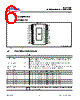
4 / 30 page  Data Sheet 4 Rev. 1.0, 2011-03-23 TLE 8108 EM Smart 8-Channel Low Side Switch Overview Diagnostic Feedback Information • Latched diagnostic information via SPI register • Overtemperature detection (DOT) • Overload detection corresponding Short Circuit to Battery (SCB) in ON state. • Open load detection in OFF state (OL) • Short Circuit to GND detection in OFF state (SCG) Protection Functions • Overload switch off • Overtemperature switch off • Electrostatic discharge (ESD) Application • Resistive, inductive and capacitive loads • Especially designed for driving relays in automotive applications General Information The TLE8108EM is an 8-Channel Low Side Relay Switch designed for typical automotive relays, providing embedded protective functions. The PG-SSOP-24 package is used to get a footprint optimized solution. The 16 bit serial peripheral interface (SPI) is utilized for control and diagnosis of the device and the loads. The SPI interface provides daisy chain capability. The TLE8108EM is equipped with 4 input pins that can be used to directly control their dedicated channels thus offering flexibility in design and PCB layout. The input multiplexer is controlled via SPI. The device provides full diagnosis of the load, which is open load, short circuit to ground, as well as a short circuit to battery detection. The SPI diagnosis bits indicate latched fault conditions that may have occurred. Each output stage is protected against short circuit. In case of Overload, the affected channel switches off. There are temperature sensors for each channel to protect the device in case of Overtemperature. The device is supplied by a single power supply. It is operating at 5V nominal value. The internal switches are power n-MOSFETs. The inputs are ground referenced CMOS compatible. The device is monolithically integrated in Smart Power Technology. All output pins are available at one side of the device while the other side bundles the signals to the microcontroller, thus facilitating the PCB layout. It is possible to set each channel in a Clear Mode (CLR) in order to clear Diagnosis flags; in CLR state output is switched off and diagnosis currents are disabled. A Standby mode of the Device (STB) can be entered if all the channels are set into CLR state; in STB mode the power consumpiton is reduced to the minimum. |
|
|
链接网址 |
| ALLDATASHEET是否为您带来帮助? [ DONATE ] |
关于 Alldatasheet | 广告服务 | 联系我们 | 隐私政策 | 数据表链接 | 链接交换 | 制造商名单 All Rights Reserved©Alldatasheet.com |
| Russian : Alldatasheetru.com | Korean : Alldatasheet.co.kr | Spanish : Alldatasheet.es | French : Alldatasheet.fr | Italian : Alldatasheetit.com Portuguese : Alldatasheetpt.com | Polish : Alldatasheet.pl | Vietnamese : Alldatasheet.vn Indian : Alldatasheet.in | Mexican : Alldatasheet.com.mx | British : Alldatasheet.co.uk | New Zealand : Alldatasheet.co.nz |
|
Family Site : ic2ic.com |
icmetro.com |
 Chinese ▼
 English
 Chinese
 German
 Japanese
 Russian
 Korean
 Spanish
 French
 Italian
 Portuguese
 Polish
 Vietnamese
 Indian
 Mexican
 British
 New Zealand