|
数据搜索系统,热门电子元器件搜索 |
|
|
数据搜索系统,热门电子元器件搜索 |
|
FT51AL-R 数据表(PDF) 14 Page - Future Technology Devices International Ltd. |
|
|
|||||||||||||||||||||||||||||
FT51AL-R 数据表(HTML) 14 Page - Future Technology Devices International Ltd. |
|
|
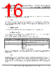
14 / 43 page  Copyright © Future Technology Devices International Limited 14 FT51A Advanced MCU with 8051 Compatible Core IC Datasheet Version 1.5 Doc ument N o.: FT _000877 C learance N o.: FT DI#420 3.2.11 USB XCVR The USB Transceiver Cell provides the USB 2.0 full-speed physical interface to the USB cable. The output drivers provide +3.3V level slew rate control signalling, whilst a differential input receiver and two single ended input receivers provide USB data in, Single -Ended-0 (SE0) and USB reset detection conditions respectfully. This function also incorporates a 1.5kΩ pull up resistor on the USBUPDP pin. 3.2.12 IO Multiplexer With the addition of the IO multiplexer any function can be configured to any DIO pin, excluding the analogue ADC function which is constrained to the AIO pins. All other digital functionality is recommended to map to DIO pins. The IO multiplexer allows the designer to select which peripherals are connected to which IO pins. In order to assign a signal to a particular pin, two register writes are required, one to select the signal and the other to select the IO pin. The FT51A Programmer’s Guide details the pins and signals which can be connected. The selectable peripheral interfaces are only limited by the number of IO pins available. The number of IOs available is dependent on the package type. Table 3-2 lists the peripherals which can be multiplexed to IO and the typical number of pins required for each one. The designer can choose any mix of peripheral configurations as long as they are within the specific package IO pin count. Peripherals Number of pins required (typical) UART (FTDI) 4 UART (8051) 2 ADC 1-16 8051 Port 0-3 32 SPI Master 4 SPI Slave 4 245 FIFO 12 I2C Master 2 I2C Slave 2 PWM 1-8 Table 3-2 – Peripheral Pin Requirements 3.2.13 I2C Master The FT51A provides an interface between the core and an I2C bus. It can be programmed to operate with arbitration and clock synchronization allowing it to operate in multi‐master systems. I2C Master supports transmission speeds up to 3.4 Mb/s including Normal, Fast and High Speed modes . |
|
链接网址 |
| ALLDATASHEET是否为您带来帮助? [ DONATE ] |
关于 Alldatasheet | 广告服务 | 联系我们 | 隐私政策 | 数据表链接 | 链接交换 | 制造商名单 All Rights Reserved©Alldatasheet.com |
| Russian : Alldatasheetru.com | Korean : Alldatasheet.co.kr | Spanish : Alldatasheet.es | French : Alldatasheet.fr | Italian : Alldatasheetit.com Portuguese : Alldatasheetpt.com | Polish : Alldatasheet.pl | Vietnamese : Alldatasheet.vn Indian : Alldatasheet.in | Mexican : Alldatasheet.com.mx | British : Alldatasheet.co.uk | New Zealand : Alldatasheet.co.nz |
|
Family Site : ic2ic.com |
icmetro.com |
 Chinese ▼
 English
 Chinese
 German
 Japanese
 Russian
 Korean
 Spanish
 French
 Italian
 Portuguese
 Polish
 Vietnamese
 Indian
 Mexican
 British
 New Zealand