|
数据搜索系统,热门电子元器件搜索 |
|
|
数据搜索系统,热门电子元器件搜索 |
|
P9221-R 数据表(PDF) 20 Page - Integrated Device Technology |
|
|
|||||||||||||||||||||||||||||
P9221-R 数据表(HTML) 20 Page - Integrated Device Technology |
|
|
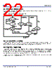
20 / 35 page  P9221-R Datasheet © 2017 Integrated Device Technology, Inc. 20 April 4, 2017 9. Communication Interface 9.1 Modulation/Communication The wireless medium power charging system uses two-way communication: receiver-to-transmitter and transmitter-to receiver. Receiver-to-transmitter communication is accomplished by modulating the load seen by the receiver's inductor; the communication is purely digital and symbols 1’s and 0’s ride on top of the power signal that exists between the two coils. Modulation is done with amplitude-shift keying (ASK) modulation using internal switches to connect external capacitors from AC1 and AC2 to ground (see Figure 17) with a bit rate of 2Kbps. To the transmitter, this appears as an impedance change, which results in measurable variations of the transmitter’s output waveform. The power transmitter detects this as a modulation of coil current/voltage to receive the packets. Transmitter-to-receiver communication is accomplished by frequency-shift keying (FSK) modulation over the power signal frequency. The power receiver P9221-R has the means to demodulate FSK data from the power signal frequency and use it in order to establish the handshaking protocol with the power transmitter. The P9221-R implements FSK communication when used in conjunction with WPC-compliant transmitters, such as the P9242-R. The FSK communication protocol allows the transmitter to send data to the receiver using the power transfer link in the form of modulating the power transfer signal. This modulation appears in the form of a change in the base operating frequency (fOP) to the modulated operating frequency (fMOD) in periods of 256 consecutive cycles. Equation 2 should be used to compute the modulated frequency based on any given operating frequency. The P9221-R will only implement positive FSK polarity adjustments; in other words, the modulated frequency will always be higher than the operating frequency during FSK communication. Communication packets are transmitted from transmitter to receiver with less than 1% positive frequency deviation following any receiver-to- transmitter communication packet. The frequency deviation is calculated using Equation 2. fMOD= 60000 60000 fOP − 3 [KHz] Equation 2 Where fMOD is the changed frequency in the power signal frequency; fOP is the base operating frequency of the power transfer; and 60000kHz is the internal oscillator responsible for counting the period of the power transfer signal. The FSK byte-encoding scheme and packet structure comply with the WPC specification revision 1.2.2. The FSK communication uses a bi-phase encoding scheme to modulate data bits into the power transfer signal. The start bit will consist of 512 consecutive fMOD cycles (or logic ‘0’). A logic ‘1’ value will be sent by sending 256 consecutive fOP cycles followed by 256 fMOD cycles or vice versa, and a logic ‘0’ is sent by sending 512 consecutive fMOD or fOP cycles. Figure 18. Example of Differential Bi-phase Decoding for FSK tCLK = 256/fOP ONE ZERO ONE ZERO ONE ONE ZERO ZERO 512 cycles 256 cycles Each byte will comply with the start, data, parity, and stop asynchronous serial format structure shown in Figure 19: Figure 19. Example of Asynchronous Serial Byte Format for FSK Start Stop Parity b 0 1 2 3 4 5 6 7 b b b b b b b |
|
链接网址 |
| ALLDATASHEET是否为您带来帮助? [ DONATE ] |
关于 Alldatasheet | 广告服务 | 联系我们 | 隐私政策 | 数据表链接 | 链接交换 | 制造商名单 All Rights Reserved©Alldatasheet.com |
| Russian : Alldatasheetru.com | Korean : Alldatasheet.co.kr | Spanish : Alldatasheet.es | French : Alldatasheet.fr | Italian : Alldatasheetit.com Portuguese : Alldatasheetpt.com | Polish : Alldatasheet.pl | Vietnamese : Alldatasheet.vn Indian : Alldatasheet.in | Mexican : Alldatasheet.com.mx | British : Alldatasheet.co.uk | New Zealand : Alldatasheet.co.nz |
|
Family Site : ic2ic.com |
icmetro.com |
 Chinese ▼
 English
 Chinese
 German
 Japanese
 Russian
 Korean
 Spanish
 French
 Italian
 Portuguese
 Polish
 Vietnamese
 Indian
 Mexican
 British
 New Zealand