|
数据搜索系统,热门电子元器件搜索 |
|
|
数据搜索系统,热门电子元器件搜索 |
|
AD7980BCPZ-R2 数据表(PDF) 18 Page - Analog Devices |
|
|
|||||||||||||||||||||||||||||
AD7980BCPZ-R2 数据表(HTML) 18 Page - Analog Devices |
|
|
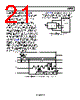
18 / 28 page  AD7980 Data Sheet Rev. F | Page 16 of 26 ANALOG INPUT Figure 28 shows an equivalent circuit of the input structure of the AD7980. The two diodes, D1 and D2, provide ESD protection for the analog inputs, IN+ and IN−. Care must be taken to ensure that the analog input signal never exceeds the supply rails by more than 0.3 V, because this causes these diodes to become forward- biased and start conducting current. These diodes can handle a forward-biased current of 130 mA maximum. For instance, these conditions could eventually occur when the supplies of the input buffer (U1) are different from VDD. In such a case (for example, an input buffer with a short circuit), the current limitation can be used to protect the device. Figure 28. Equivalent Analog Input Circuit The analog input structure allows the sampling of the true differential signal between IN+ and IN−. By using these differential inputs, signals common to both inputs are rejected. During the acquisition phase, the impedance of the analog inputs (IN+ and IN−) can be modeled as a parallel combination of capacitor, CPIN, and the network formed by the series connection of RIN and CIN. CPIN is primarily the pin capacitance. RIN is typically 400 Ω and is a lumped component made up of some serial resistors and the on resistance of the switches. CIN is typically 30 pF and is mainly the ADC sampling capacitor. During the conversion phase, where the switches are opened, the input impedance is limited to CPIN. RIN and CIN make a 1-pole, low-pass filter that reduces undesirable aliasing effects and limits the noise. When the source impedance of the driving circuit is low, the AD7980 can be driven directly. Large source impedances significantly affect the ac performance, especially THD. The dc performances are less sensitive to the input impedance. The maximum source impedance depends on the amount of THD that can be tolerated. The THD degrades as a function of the source impedance and the maximum input frequency. DRIVER AMPLIFIER CHOICE Although the AD7980 is easy to drive, the driver amplifier needs to meet the following requirements: The noise generated by the driver amplifier needs to be kept as low as possible to preserve the SNR and transition noise performance of the AD7980. The noise coming from the driver is filtered by the 1-pole, low-pass filter of the AD7980 analog input circuit made by RIN and CIN or by the external filter, if one is used. Because the typical noise of the AD7980 is 47.3 μV rms, the SNR degradation due to the amplifier is 2 3dB 2 ) ( 2 π 47.3 47.3 log 20 N LOSS Ne f SNR where: f–3dB is the input bandwidth in MHz of the AD7980 (10 MHz) or the cutoff frequency of the input filter, if one is used. N is the noise gain of the amplifier (for example, 1 in buffer configuration). eN is the equivalent input noise voltage of the op amp, in nV/√Hz. For ac applications, the driver should have a THD performance commensurate with the AD7980. For multichannel multiplexed applications, the driver amplifier and the AD7980 analog input circuit must settle for a full-scale step onto the capacitor array at a 16-bit level (0.0015%, 15 ppm). In the amplifier data sheet, settling at 0.1% to 0.01% is more commonly specified. This can differ significantly from the settling time at a 16-bit level and should be verified prior to driver selection. Table 9. Recommended Driver Amplifiers1 Amplifier Typical Application ADA4805-1 Low noise, small size, and low power ADA4807-1 Very low noise and high frequency ADA4627-1 Precision, low noise, and low input bias current ADA4522-1 Precision, zero drift, and EMI enhanced ADA4500-2 Precision, rail-to-rail input/output, and zero input crossover distortion 1 For the latest recommended drivers, see the product recommendations listed on the product webpage. REF RIN CIN IN+ OR IN– GND D2 CPIN D1 |
|
|
链接网址 |
| ALLDATASHEET是否为您带来帮助? [ DONATE ] |
关于 Alldatasheet | 广告服务 | 联系我们 | 隐私政策 | 数据表链接 | 链接交换 | 制造商名单 All Rights Reserved©Alldatasheet.com |
| Russian : Alldatasheetru.com | Korean : Alldatasheet.co.kr | Spanish : Alldatasheet.es | French : Alldatasheet.fr | Italian : Alldatasheetit.com Portuguese : Alldatasheetpt.com | Polish : Alldatasheet.pl | Vietnamese : Alldatasheet.vn Indian : Alldatasheet.in | Mexican : Alldatasheet.com.mx | British : Alldatasheet.co.uk | New Zealand : Alldatasheet.co.nz |
|
Family Site : ic2ic.com |
icmetro.com |
 Chinese ▼
 English
 Chinese
 German
 Japanese
 Russian
 Korean
 Spanish
 French
 Italian
 Portuguese
 Polish
 Vietnamese
 Indian
 Mexican
 British
 New Zealand