|
数据搜索系统,热门电子元器件搜索 |
|
|
数据搜索系统,热门电子元器件搜索 |
|
CC1070-RTY1 数据表(PDF) 13 Page - Texas Instruments |
|
|
|
|||||||||||||||||||||||||||||
CC1070-RTY1 数据表(HTML) 13 Page - Texas Instruments |
|
|
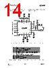
13 / 57 page  CC1070 SWRS043 Page 13 of 58 6 Circuit Description BIAS DI LOCK PDO DCLK FREQ SYNTH DIGITAL MODULATOR - Modulation - Data shaping - Power Control Power Control DIGITAL INTERFACE TO µC RF_OUT R_BIAS XOSC_Q1 XOSC_Q2 XOSC VC CHP_OUT :2 :2 Multiplexer PCLK PDI PSEL Figure 2. CC1070 simplified block diagram A simplified block diagram of CC1070 is shown in Figure 2. Only signal pins are shown. During transmit operation, the synthesized RF frequency is fed directly to the power amplifier (PA). The RF output is frequency shift keyed (FSK) by the digital bit stream that is fed to the DI pin. Optionally, the internal Gaussian filter can be enabled for Gaussian FSK (GFSK). The frequency synthesizer includes a completely on-chip LC VCO. The VCO operates in the frequency range 1.608- 1.880 GHz. The CHP_OUT pin is the charge pump output and VC is the control node of the on-chip VCO. The external loop filter is placed between these pins. A crystal is to be connected between XOSC_Q1 and XOSC_Q2. A lock signal is available from the PLL. The 4-wire SPI serial interface is used for configuration. 7 Application Circuit Very few external components are required for the operation of CC1070. A typical application circuit is shown in Figure 3. The external components are described in Table 9 and values are given in Table 10. Output matching L2, C2 and C3 are used to match the transmitter to 50 Ω. See section 13 on page 26 for details. Component values for the matching network are easily calculated using the SmartRF® Studio software. Bias resistor The precision bias resistor R1 is used to set an accurate bias current. PLL loop filter The loop filter consists of two resistors (R2 and R3) and three capacitors (C6-C8). C7 and C8 may be omitted in applications where high loop bandwidth is desired. The values shown in Table 10 can be used for data rates up to 4.8 kBaud. Component values for higher data rates are easily found using the SmartRF® Studio software. Crystal An external crystal with two loading capacitors (C4 and C5) is used for the crystal oscillator. See section 17 on page 34 for details. Additional filtering Additional external components (e.g. RF LC or SAW filter) may be used in order to improve the performance in specific applications. See section 13 on page 26 for further information. Power supply decoupling and filtering Power supply decoupling and filtering must be used (not shown in the application circuit). The placement and size of the decoupling capacitors and the power supply filtering are very important to |
|
链接网址 |
| ALLDATASHEET是否为您带来帮助? [ DONATE ] |
关于 Alldatasheet | 广告服务 | 联系我们 | 隐私政策 | 数据表链接 | 链接交换 | 制造商名单 All Rights Reserved©Alldatasheet.com |
| Russian : Alldatasheetru.com | Korean : Alldatasheet.co.kr | Spanish : Alldatasheet.es | French : Alldatasheet.fr | Italian : Alldatasheetit.com Portuguese : Alldatasheetpt.com | Polish : Alldatasheet.pl | Vietnamese : Alldatasheet.vn Indian : Alldatasheet.in | Mexican : Alldatasheet.com.mx | British : Alldatasheet.co.uk | New Zealand : Alldatasheet.co.nz |
|
Family Site : ic2ic.com |
icmetro.com |
 Chinese ▼
 English
 Chinese
 German
 Japanese
 Russian
 Korean
 Spanish
 French
 Italian
 Portuguese
 Polish
 Vietnamese
 Indian
 Mexican
 British
 New Zealand