|
数据搜索系统,热门电子元器件搜索 |
|
|
数据搜索系统,热门电子元器件搜索 |
|
T48C862M-R3 数据表(PDF) 24 Page - ATMEL Corporation |
|
|
|||||||||||||||||||||||||||||
T48C862M-R3 数据表(HTML) 24 Page - ATMEL Corporation |
|
|
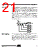
24 / 107 page  24 T48C862-R3 4554A–4BMCU–02/03 Figure 18. Internal Supply Voltage Supervisor Figure 19. External Input Voltage Supervisor Clock Generation Clock Module The T48C862-R3 contains a clock module with 4 different internal oscillator types: two RC-oscillators, one 4-MHz crystal oscillator and one 32-kHz crystal oscillator. The pins OSC1 and OSC2 are the interface to connect a crystal either to the 4-MHz, or to the 32-kHz crystal oscillator. OSC1 can be used as input for external clocks or to connect an external trimming resistor for the RC-oscillator 2. All necessary circuitry, except the crys- tal and the trimming resistor, is integrated on-chip. One of these oscillator types or an external input clock can be selected to generate the system clock (SYSCL). In applications that do not require exact timing, it is possible to use the fully integrated RC-oscillator 1 without any external components. The RC-oscillator 1 center frequency tolerance is better than ± 50%. The RC-oscillator 2 is a trimmable oscillator whereby the oscillator frequency can be trimmed with an external resistor attached between OSC1 and V DD. In this configuration, the RC-oscillator 2 frequency can be maintained stable with a tolerance of ± 15% over the full operating temperature and voltage range. The clock module is programmable via software with the clock management register (CM) and the system configuration register (SC). The required oscillator configuration can be selected with the OS1-bit and the OS0-bit in the SC-register. A programmable 4-bit divider stage allows the adjustment of the system clock speed. A special feature of the clock management is that an external oscillator may be used and switched on and off via a port pin for the power-down mode. Before the external clock is switched off, the internal RC-oscillator 1 must be selected with the CCS-bit and then the SLEEP mode may be activated. In this state an interrupt can wake up the controller with the RC-oscil- lator, and the external oscillator can be activated and selected by software. A synchronization stage avoids too short clock periods if the clock source or the clock speed is changed. If an external input clock is selected, a supervisor circuit monitors the external input and generates a hardware reset if the external clock source fails or drops below 500 kHz for more than 1 ms. V DD Low threshold Middle threshold High threshold VMS = 1 Low threshold Middle threshold High threshold VMS = 0 3.0 V 2.6 V 2.2 V 1.3 V VMI VMS = 1 VMS = 0 Positive slope Negative slope VMS = 1 VMS = 0 Interrupt negative slope Interrupt positive slope Internal reference level t |
|
链接网址 |
| ALLDATASHEET是否为您带来帮助? [ DONATE ] |
关于 Alldatasheet | 广告服务 | 联系我们 | 隐私政策 | 数据表链接 | 链接交换 | 制造商名单 All Rights Reserved©Alldatasheet.com |
| Russian : Alldatasheetru.com | Korean : Alldatasheet.co.kr | Spanish : Alldatasheet.es | French : Alldatasheet.fr | Italian : Alldatasheetit.com Portuguese : Alldatasheetpt.com | Polish : Alldatasheet.pl | Vietnamese : Alldatasheet.vn Indian : Alldatasheet.in | Mexican : Alldatasheet.com.mx | British : Alldatasheet.co.uk | New Zealand : Alldatasheet.co.nz |
|
Family Site : ic2ic.com |
icmetro.com |
 Chinese ▼
 English
 Chinese
 German
 Japanese
 Russian
 Korean
 Spanish
 French
 Italian
 Portuguese
 Polish
 Vietnamese
 Indian
 Mexican
 British
 New Zealand