|
数据搜索系统,热门电子元器件搜索 |
|
|
数据搜索系统,热门电子元器件搜索 |
|
SSM2302CPZ-R2 数据表(PDF) 12 Page - Analog Devices |
|
|
|||||||||||||||||||||||||||||
SSM2302CPZ-R2 数据表(HTML) 12 Page - Analog Devices |
|
|
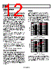
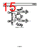
12 / 20 page  SSM2302 Rev. 0 | Page 12 of 20 APPLICATION NOTES OVERVIEW The SSM2302 stereo Class-D audio amplifier features a filterless modulation scheme that greatly reduces the external components count, conserving board space and thus reducing systems cost. The SSM2302 does not require an output filter, but instead relies on the inherent inductance of the speaker coil and the natural filtering of the speaker and human ear to fully recover the audio component of the square-wave output. While most Class-D ampli- fiers use some variation of pulse-width modulation (PWM), the SSM2302 uses a Σ-Δ modulation to determine the switching pattern of the output devices. This provides a number of important benefits. Σ-Δ modulators do not produces a sharp peak with many harmonics in the AM frequency band, as pulse-width modulators often do. Σ-Δ modulation provides the benefits of reducing the amplitude of spectral components at high frequencies; that is, reducing EMI emission that might otherwise be radiated by speakers and long cable traces. The SSM2302 also offers protection circuits for overcurrent and temperature protection. GAIN SELECTION Pulling the GAIN pin high of the SSM2302 sets the gain of the speaker amplifier to 12 dB; pulling it low sets the gain of the speaker amplifier to 6 dB. It is possible to adjust the SSM2302 gain by using external resistors at the input. To set a gain lower than 12 dB refer to Figure 22 for differential input configuration and Figure 23 for single-ended configuration. For external gain configuration from a fixed 12 dB gain, please use the following formula: External Gain Settings = 20 log[4/(1 + R/150 kΩ)] To set a gain lower than 6 dB refer to Figure 24 for differential input configuration and Figure 25 for single-ended configuration. For external gain configuration from a fixed 6 dB gain, use the following formula: External Gain Settings = 20 log[2/(1 + R/150 kΩ)] POP-AND-CLICK SUPPRESSION Voltage transients at the output of audio amplifiers can occur when shutdown is activated or deactivated. Voltage transients as low as 10 mV can be heard as an audio pop in the speaker. Clicks and pops can also be classified as undesirable audible transients generated by the amplifier system, therefore as not coming from the system input signal. Such transients can be generated when the amplifier system changes its operating mode. For example, the following can be sources of audible transients: system power-up/ power-down, mute/unmute, input source change, and sample rate change. The SSM2302 has a pop-and-click suppression architecture that reduces this output transients, resulting in noiseless activation and deactivation. EMI NOISE The SSM2302 uses a proprietary modulation and spread- spectrum technology to minimize EMI emissions from the device. Figure 26 shows SSM2302 EMI emission starting from 100 kHz to 30 MHz. Figure 27 shows SSM2302 EMI emission from 30 kHz to 2 GHz. These figures clearly describe the SSM2302 EMI behavior as being well below the FCC regulation values, starting from 100 kHz and passing beyond 1 GHz of frequency. Although the overall EMI noise floor is slightly higher, frequency spurs from the SSM2302 are greatly reduced. 70 0 0.1 100 FREQUENCY (MHz) 60 50 40 30 20 10 110 = HORIZONTAL = VERTICAL = REGULATION VALUE Figure 26. EMI Emissions from SSM2302 70 0 10 10k FREQUENCY (MHz) 60 50 40 30 20 10 100 1k = HORIZONTAL = VERTICAL = REGULATION VALUE Figure 27. EMI Emissions from SSM2302 The measurements for Figure 26 and Figure 27 were taken with a 1 kHz input signal, producing 0.5 W output power into an 8 Ω load from a 3.6 V supply. Cable length was approximately 5 cm. The EMI was detected using a magnetic probe touching the 2” output trace to the load. |
|
|
链接网址 |
| ALLDATASHEET是否为您带来帮助? [ DONATE ] |
关于 Alldatasheet | 广告服务 | 联系我们 | 隐私政策 | 数据表链接 | 链接交换 | 制造商名单 All Rights Reserved©Alldatasheet.com |
| Russian : Alldatasheetru.com | Korean : Alldatasheet.co.kr | Spanish : Alldatasheet.es | French : Alldatasheet.fr | Italian : Alldatasheetit.com Portuguese : Alldatasheetpt.com | Polish : Alldatasheet.pl | Vietnamese : Alldatasheet.vn Indian : Alldatasheet.in | Mexican : Alldatasheet.com.mx | British : Alldatasheet.co.uk | New Zealand : Alldatasheet.co.nz |
|
Family Site : ic2ic.com |
icmetro.com |
 Chinese ▼
 English
 Chinese
 German
 Japanese
 Russian
 Korean
 Spanish
 French
 Italian
 Portuguese
 Polish
 Vietnamese
 Indian
 Mexican
 British
 New Zealand