|
数据搜索系统,热门电子元器件搜索 |
|
|
数据搜索系统,热门电子元器件搜索 |
|
FD-R34EG 数据表(PDF) 21 Page - List of Unclassifed Manufacturers |
|
|
|||||||||||||||||||||||||||||
FD-R34EG 数据表(HTML) 21 Page - List of Unclassifed Manufacturers |
|
|
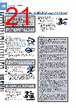
21 / 28 page  159 DigitalFiberSensorFX-300SERIES Selection Guide Fibers Fiber Amplifiers FX-500 FX-100 FX-300 FX-410 FX-311 FX-301-F7/ FX-301-F FIBER SENSORS LASER SENSORS PHOTO- ELECTRIC SENSORS MICRO PHOTO- ELECTRIC SENSORS AREA SENSORS LIGHT CURTAINS / SAFETY COMPONENTS PRESSURE / FLOW SENSORS INDUCTIVE PROXIMITY SENSORS PARTICULAR USE SENSORS SENSOR OPTIONS SIMPLE WIRE-SAVING UNITS WIRE-SAVING SYSTEMS MEASURE- MENT SENSORS STATIC ELECTRICITY PREVENTION DEVICES LASER MARKERS PLC HUMAN MACHINE INTERFACES ENERGY CONSUMPTION VISUALIZATION COMPONENTS FA COMPONENTS MACHINE VISION SYSTEMS UV CURING SYSTEMS Cascading • Make sure that the power supply is off while adding or removing the amplifiers. • Make sure to check the allowable ambient temperature, as it depends on the number of amplifiers connected in cascade. • In case two, or more, amplifiers are connected in cascade, make sure to mount them on a DIN rail. • When the amplifiers move on the DIN rail depending on the attaching condition or the amplifiers are mounted close to each other in cascade, fit them between the optional end plates ( MS-DIN-E) mounted at the two ends. • Up to maximum 15 amplifiers can be added (total 16 amplifiers connected in cascade.) • When connecting more than two amplifiers in cascade, use the sub cable ( CN-71-C□ / CN-72-C□) as the quick-connection cable for the second amplifier onwards. • When connecting amplifiers not close to each other in parallel, be sure to mount the optional end plate ( MS-DIN-E) at both sides of each amplifier or affix the communication window seal of the accessory amplifier protection seal ( FX-MB1) to the communication windows. • The settings other than the interference prevention function cannot be transmitted between FX-301(P) FX-301B/G/H(P), FX-305(P). Therefore, in case both models of amplifiers are mounted in cascade, be sure to mount identical models together. However, the interference prevention function is not incorporated in the FX-301(P)-HS. Take care when the sensors are mounted in cascade. • If the FX-301(P) updated version unit or the FX-305(P) is mounted with the FX-301(P) previous version unit or the FX-301B/G/H(P) in cascade, place the FX-301(P) updated version units and the FX-305(P) units to the right side (seen from the connector side) of the previous version units. For details, refer to “ Cautions on sensor connection in cascade”. For a difference between the updated version unit and the previous version unit, refer to “ A difference between the updated version unit and the previous version unit”. • The communication function of this product and that of the FX-301(P)-F / F7 is different. If these models are mounted in cascade, affix the accessory fiber amplifier protection seal ( FX-MB1) included in the FX-301(P) and FX-305(P) to the communication windows of the amplifiers. Mounting Connection PRECAUTIONS FOR PROPER USE Refer to p.1458~ for general precautions and to the “PRO mode operation guide” on our website for details pertaining to operating instructions for the amplifier. • The digital fiber sensor FX-301(P) has been modified since its production in June 2004. The explanations below are about the modified product. • Never use this product as a sensing device for personnel protection. • In case of using sensing devices for personnel protection, use products which meet laws and standards, such as OSHA, ANSI or IEC etc., for personnel protection applicable in each region or country. Disconnection method Projection How to mount the amplifier Fit the rear part of the mounting section of the amplifier on a 35 mm 1.378 in width DIN rail. Press down the rear part of the mounting section of the unit on the 35 mm 1.378 in width DIN rail and fit the front part of the mounting section to the 35 mm 1.378 in width DIN rail. How to remove the amplifier Push the amplifier forward. Lift up the front part of the amplifier to remove it. Note: Take care that if the front part is lifted without pushing the amplifier forward, the hook on the rear portion of the mounting section is likely to break. Fiber installation • Insert the fiber into the amplifier after attaching the attachment. Refer to the "Instruction Manual" included with the fiber for details. • Make sure that the power supply is off while connecting or disconnecting the quick-connection cable. 35 mm 1.378 in width DIN rail Push the fiber lock lever down. Slowly insert the fiber into the insertion slot until it stops. (Note 1) Push the fiber lock lever back up until it stops. Holding the connector of the quick-connection cable, align its projection with the groove at the top portion of the amplifier connector. Insert the connector till a click is felt. Notes: 1) Note that if the fiber is not fully inserted, the sensing distance will decrease. Also note that the flexible fiber may bend during insertion. 2) In case of coaxial reflective type fibers ( FD-G4, FD-FM2, etc.), mount the central fiber (single-core) to the emitter part and the peripheral fiber (multi-core) to the receiver. Note that sensing precision will deteriorate when done in reverse. Fiber Fiber lock lever Connection method Groove Projection Quick-connection cable Pressing the projection at the top of the quick-connection cable, pull out the connector. Note: Take care that if the connector is pulled out without pressing the projection, the projection may break. Do not use a quick-connection cable whose projection has broken. Further, do not pull by holding the cable, as this can cause a cable-break. |
|
|
链接网址 |
| ALLDATASHEET是否为您带来帮助? [ DONATE ] |
关于 Alldatasheet | 广告服务 | 联系我们 | 隐私政策 | 数据表链接 | 链接交换 | 制造商名单 All Rights Reserved©Alldatasheet.com |
| Russian : Alldatasheetru.com | Korean : Alldatasheet.co.kr | Spanish : Alldatasheet.es | French : Alldatasheet.fr | Italian : Alldatasheetit.com Portuguese : Alldatasheetpt.com | Polish : Alldatasheet.pl | Vietnamese : Alldatasheet.vn Indian : Alldatasheet.in | Mexican : Alldatasheet.com.mx | British : Alldatasheet.co.uk | New Zealand : Alldatasheet.co.nz |
|
Family Site : ic2ic.com |
icmetro.com |
 Chinese ▼
 English
 Chinese
 German
 Japanese
 Russian
 Korean
 Spanish
 French
 Italian
 Portuguese
 Polish
 Vietnamese
 Indian
 Mexican
 British
 New Zealand