|
数据搜索系统,热门电子元器件搜索 |
|
|
数据搜索系统,热门电子元器件搜索 |
|
AD8146ACPZ-R2 数据表(PDF) 20 Page - Analog Devices |
|
|
|||||||||||||||||||||||||||||
AD8146ACPZ-R2 数据表(HTML) 20 Page - Analog Devices |
|
|
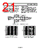
20 / 24 page  AD8146/AD8147/AD8148 Rev. 0 | Page 20 of 24 20 Under no circumstances should capacitance be intentionally added to an output to introduce frequency domain peaking. Figure 36 and Figure 37 illustrate how adding just 5 pF of excessive load capacitance influences time and frequency domain responses. 2.0 –2.0 0 TIME (ns) 1.5 1.0 0.5 0 –0.5 –1.0 –1.5 2 4 6 8 10121416 18 VS = ±5V RL, dm = 200Ω VOUT, dm = 2V p-p CL = 5pF CL = 0pF Figure 36. Large Signal Transient Responses at Various Capacitive Loads 12 2 10 1000 FREQUENCY (MHz) 100 11 10 9 8 7 6 5 4 3 VS = ±5V RL, dm = 200Ω VOUT, dm = 2V p-p CL = 5pF CL = 0pF Figure 37. Large Signal Frequency Responses at Various Capacitive Loads While high frequency peaking is desirable in some cable equalization applications, it should be implemented using methods that do not compromise the stability of the driver and that do not depend on amplifier parasitic elements. The parasitic elements are affected by process variations and cannot be depended upon for circuit designs. The amplifier may break into oscillation when excess load capacitance is intentionally added. For more information on this topic, see the Adding Pre- Emphasis to the AD8148 section for a description on how to introduce a controlled amount of pre-emphasis for 30 meters of UTP using the AD8148. ADDING PRE-EMPHASIS TO THE AD8148 UTP cables exhibit loss characteristics that are low pass in nature and are exponential functions of the square root of the frequency. Over wideband video bandwidths, the losses are predominantly due to the skin effect, which causes the resistance of the cable to increase with frequency. Even though the loss characteristics are nonlinear, suitable linear networks can be designed to approximately compensate for the losses. Placing the compensation network at the transmitting end of the cable is referred to as pre-emphasis, because the higher frequencies are emphasized, or boosted, before they are sent, to compensate for the low-pass response of the cable. Because the higher frequencies experience more loss than the lower frequencies as they pass through the cable, the high and low frequencies arrive at approximately the same level and at the end of the cable when a properly designed pre-emphasis network is used at the transmitter. The ideal cascaded frequency response of the pre- emphasis network and the cable is therefore nominally flat. Because the AD8148 has an internally set, closed-loop gain of 4 (12 dB), it is possible to reduce the gain at low frequencies using external frequency selective components, then use these components to provide increasing gain with increasing frequency, back to a value close to 12 dB. These components, along with the AD8148, form the pre-emphasis network. When properly designed, the combined frequency response of the pre-emphasis network and cable is approximately flat with a gain of 2 (6 dB). Figure 38 illustrates how to construct a pre-emphasis network using the AD8148 that compensates for 30 meters of UTP cable. The network in the lower leg is required to match the transfer function of the two feedback loops. At dc, the capacitors are open circuits, and the network has a gain of approximately 6.5 dB. (The additional 0.5 dB is added to compensate for the cable flat loss that occurs at frequencies below where the skin effect begins to take effect.) Moving up in frequency, the 30 pF capacitor begins to take effect and introduces a zero into the frequency response, causing the gain to increase with frequency. Continuing to move up in frequency, the 30 pF capacitor becomes an effective short, and the 487 Ω resistor goes in parallel with the 442 Ω resistor, forming a pole in the response. Continuing to move up in frequency, the 15 pF capacitor takes effect, introducing another zero, and causes the gain to further increase with frequency until it becomes an effective short, and the gain starts to flatten out until the amplifier response begins to roll off. The gain does not reach 12 dB before the amplifier begins to roll off because the 12 dB value is a high frequency asymptote. The pole and zero locations cited in the previous discussion are qualitative, but the discussion describes the basic principles involved with the operation of the pre-emphasis network. |
|
|
链接网址 |
| ALLDATASHEET是否为您带来帮助? [ DONATE ] |
关于 Alldatasheet | 广告服务 | 联系我们 | 隐私政策 | 数据表链接 | 链接交换 | 制造商名单 All Rights Reserved©Alldatasheet.com |
| Russian : Alldatasheetru.com | Korean : Alldatasheet.co.kr | Spanish : Alldatasheet.es | French : Alldatasheet.fr | Italian : Alldatasheetit.com Portuguese : Alldatasheetpt.com | Polish : Alldatasheet.pl | Vietnamese : Alldatasheet.vn Indian : Alldatasheet.in | Mexican : Alldatasheet.com.mx | British : Alldatasheet.co.uk | New Zealand : Alldatasheet.co.nz |
|
Family Site : ic2ic.com |
icmetro.com |
 Chinese ▼
 English
 Chinese
 German
 Japanese
 Russian
 Korean
 Spanish
 French
 Italian
 Portuguese
 Polish
 Vietnamese
 Indian
 Mexican
 British
 New Zealand