|
数据搜索系统,热门电子元器件搜索 |
|
|
数据搜索系统,热门电子元器件搜索 |
|
SSM2306CPZ-R2 数据表(PDF) 13 Page - Analog Devices |
|
|
|||||||||||||||||||||||||||||
SSM2306CPZ-R2 数据表(HTML) 13 Page - Analog Devices |
|
|
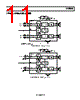
13 / 16 page  SSM2306 Rev. 0 | Page 13 of 16 LAYOUT As output power continues to increase, careful layout is needed for proper placement of PCB traces and wires between the ampli- fier, load, and power supply. A good practice is to use short, wide PCB tracks to decrease voltage drops and minimize inductance. Make track widths at least 200 mil for every inch of track length for lowest DCR, and use 1 oz. or 2 oz. of copper PCB traces to further reduce IR drops and inductance. Poor layout increases voltage drops, consequently affecting efficiency. Use large traces for the power supply inputs and amplifier outputs to minimize losses due to parasitic trace resistance. Proper grounding guide- lines help to improve audio performance, minimize crosstalk between channels, and prevent switching noise from coupling into the audio signal. To maintain high output swing and high peak output power, the PCB traces that connect the output pins to the load and supply pins should be as wide as possible to maintain the minimum trace resistances. It is also recommended to use a large area ground plane for minimum impedances. Good PCB layouts isolate critical analog paths from sources of high interference; furthermore, separate high frequency circuits (analog and digital) from low frequency ones. Properly designed multilayer printed circuit boards can reduce EMI emission and increase immunity to RF field by a factor of 10 or more compared with double-sided boards. A multilayer board allows a complete layer to be used for the ground plane, whereas the ground plane side of a double-sided board is often disrupted with signal cross- over. If the system has separate analog and digital ground and power planes, the analog ground plane should be underneath the analog power plane, and, similarly, the digital ground plane should be underneath the digital power plane. There should be no overlap between analog and digital ground planes or analog and digital power planes. INPUT CAPACITOR SELECTION The SSM2306 does not require input coupling capacitors if the input signal is biased from 1.0 V to VDD − 1.0 V. Input capacitors are required if the input signal is not biased within this recom- mended input dc common-mode voltage range, if high-pass filtering is needed (see Figure 32), or if using a single-ended source (see Figure 33). If high-pass filtering is needed at the input, the input capacitor together with the input resistor of the SSM2306 form a high-pass filter whose corner frequency is determined by the following equation: fC = 1/(2π × RIN × CIN) Input capacitors can have very important effects on the circuit performance. Not using input capacitors degrades the output offset of the amplifier as well as the PSRR performance. PROPER POWER SUPPLY DECOUPLING To ensure high efficiency, low total harmonic distortion (THD), and high PSRR, proper power supply decoupling is necessary. Noise transients on the power supply lines are short duration voltage spikes. Although the actual switching frequency can range from 10 kHz to 100 kHz, these spikes can contain fre- quency components that extend into the hundreds of megahertz. The power supply input needs to be decoupled with a good quality, low ESL and low ESR capacitor, usually around 4.7 μF. This capacitor bypasses low frequency noises to the ground plane. For high frequency transients noises, use a 0.1 μF capacitor as close as possible to the VDD pin of the device. Placing the decoupling capacitor as close as possible to the SSM2306 helps maintain efficiency performance. |
|
|
链接网址 |
| ALLDATASHEET是否为您带来帮助? [ DONATE ] |
关于 Alldatasheet | 广告服务 | 联系我们 | 隐私政策 | 数据表链接 | 链接交换 | 制造商名单 All Rights Reserved©Alldatasheet.com |
| Russian : Alldatasheetru.com | Korean : Alldatasheet.co.kr | Spanish : Alldatasheet.es | French : Alldatasheet.fr | Italian : Alldatasheetit.com Portuguese : Alldatasheetpt.com | Polish : Alldatasheet.pl | Vietnamese : Alldatasheet.vn Indian : Alldatasheet.in | Mexican : Alldatasheet.com.mx | British : Alldatasheet.co.uk | New Zealand : Alldatasheet.co.nz |
|
Family Site : ic2ic.com |
icmetro.com |
 Chinese ▼
 English
 Chinese
 German
 Japanese
 Russian
 Korean
 Spanish
 French
 Italian
 Portuguese
 Polish
 Vietnamese
 Indian
 Mexican
 British
 New Zealand