|
数据搜索系统,热门电子元器件搜索 |
|
|
数据搜索系统,热门电子元器件搜索 |
|
ADA4938-2ACPZ-R2 数据表(PDF) 21 Page - Analog Devices |
|
|
|||||||||||||||||||||||||||||
ADA4938-2ACPZ-R2 数据表(HTML) 21 Page - Analog Devices |
|
|
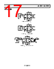
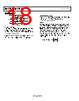
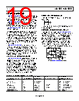
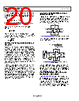
21 / 26 page  Data Sheet ADA4938-1/ADA4938-2 Rev. B | Page 21 of 26 TERMINATING A SINGLE-ENDED INPUT Using an example with an input source of 2 V, a source resistance of 50 Ω, and an overall gain of 1 V/V, four simple steps must be followed to terminate a single-ended input to the ADA4938-1/ADA4938-2. 1. The input impedance is calculated using the formula Ω 267 200) (200 2 200 1 200 2 1 F G F G IN R R R R R ADA4938 RL VO +VS –VS RS 50Ω RG 200Ω RG 200Ω RF 200Ω RF 200Ω VOCM VS 2V RIN 267Ω Figure 61. Single-Ended Input Impedance 2. To provide a 50 Ω termination for the source, the Resistor RT is calculated such that RT || RIN = 50 Ω, or RT = 61.9 Ω. ADA4938 RL VO +VS –VS RS 50Ω RG 200Ω RG 200Ω RF 200Ω RF 200Ω VOCM VS 2V 50Ω RT 61.9Ω Figure 62. Adding Termination Resistor RT 3. To compensate for the imbalance of the gain resistors, a correc- tion resistor (RTS) is added in series with the inverting Input Gain Resistor RG. RTS is equal to the Thevenin equivalent of the source resistance (RS||RT). RS 50Ω VS 2V RT 61.9Ω RTH 27.4Ω VTH 1.1V Figure 63. Calculating Thevenin Equivalent RTS = RTH = RS || RT = 27.4 Ω. Note that VTH is not equal to VS/2, which would be the case if the amplifier circuit did not affect the termination. ADA4938 RL VO 0.97V +VS –VS RTH 27.4Ω RG 200Ω RG 200Ω RF 200Ω RF 200Ω VOCM VTH 1.1V RTS 27.4Ω Figure 64. Balancing Gain Resistor RG 4. Finally, the feedback resistor is recalculated to adjust the output voltage to the desired level. a. To make the output voltage VO = 1 V, RF is calculated using Ω 207 1.1 27.4) (200 1 ) ( TH TS G O F V R R V R b. To return the overall gain to 1 V/V (VO = VS = 2 V), RF should be Ω 414 1.1 27.4) (200 2 ) ( TH TS G O F V R R V R ADA4938 RL VO +VS –VS RS 50Ω RG 200Ω RG 200Ω RF RF VOCM VS 2V RT 61.9Ω RTS 27.4Ω Figure 65. Complete Single-Ended-to-Differential System SETTING THE OUTPUT COMMON-MODE VOLTAGE The VOCM pin of the ADA4938-1/ADA4938-2 is internally biased at a voltage approximately equal to the midsupply point (average value of the voltages on V+ and V−). Relying on this internal bias results in an output common-mode voltage that is within about 100 mV of the expected value. In cases where more accurate control of the output common- mode level is required, it is recommended that an external source or resistor divider (10 kΩ or greater resistors) be used. It is also possible to connect the VOCM input to a common-mode level (CML) output of an ADC. However, care must be taken to ensure that the output has sufficient drive capability. The input impedance of the VOCM pin is approximately 10 kΩ. If multiple ADA4938-1/ADA4938-2 devices share one reference output, it is recommended that a buffer be used. |
|
|
链接网址 |
| ALLDATASHEET是否为您带来帮助? [ DONATE ] |
关于 Alldatasheet | 广告服务 | 联系我们 | 隐私政策 | 数据表链接 | 链接交换 | 制造商名单 All Rights Reserved©Alldatasheet.com |
| Russian : Alldatasheetru.com | Korean : Alldatasheet.co.kr | Spanish : Alldatasheet.es | French : Alldatasheet.fr | Italian : Alldatasheetit.com Portuguese : Alldatasheetpt.com | Polish : Alldatasheet.pl | Vietnamese : Alldatasheet.vn Indian : Alldatasheet.in | Mexican : Alldatasheet.com.mx | British : Alldatasheet.co.uk | New Zealand : Alldatasheet.co.nz |
|
Family Site : ic2ic.com |
icmetro.com |
 Chinese ▼
 English
 Chinese
 German
 Japanese
 Russian
 Korean
 Spanish
 French
 Italian
 Portuguese
 Polish
 Vietnamese
 Indian
 Mexican
 British
 New Zealand