|
数据搜索系统,热门电子元器件搜索 |
|
|
数据搜索系统,热门电子元器件搜索 |
|
ADL5902ACPZ-R7 数据表(PDF) 21 Page - Analog Devices |
|
|
|||||||||||||||||||||||||||||
ADL5902ACPZ-R7 数据表(HTML) 21 Page - Analog Devices |
|
|
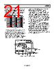
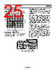
21 / 28 page  Data Sheet ADL5902 Rev. B | Page 21 of 28 Figure 46 shows how output noise varies with CLPF when the ADL5902 is driven by a single-carrier W-CDMA signal (Test Model TM1-64, peak envelope power = 10.56 dB, bandwidth = 3.84 MHz). With a 10 μF capacitor on CLPF, there is residual noise on VOUT of 4.4 mV p-p, which is less than 0.1 dB error (assuming a slope of approximately 53 mV/dB). 1 10 100 1k 10k 100k 1M 0 50 100 150 200 250 300 1 10 100 1000 CLPF (nF) OUTPUT NOISE (mV p-p) 10% TO 90% RISE TIME (µs) 90% TO 10% FALL TIME (µs) Figure 46. Output Noise, Rise and Fall Times vs. CLPF Capacitance, Single- Carrier W-CDMA (TM1-64) at 2.14 GHz with PIN = 0 dBm Figure 46 also shows how CLPF affects the response time of VOUT. To measure this, a RF burst at 2.14 GHz at −10 dBm was applied to the ADL5902. The 10% to 90% rise time and 90% to 10% fall time is then measured. It is notable that the fall time is much longer than the rise time. This can also be seen in the response time plots, Figure 22, Figure 23, Figure 25, and Figure 26. In applications where the response time is critical, a different approach to signal filtering can be taken. This is shown in Figure 47. The capacitor on the CLPF pin is set to the minimum value that ensures that a valid rms computation is performed. The job of noise removal is then handed off to an RC filter on the VOUT pin. This approach ensures that there is enough averaging to ensure good rms compliance and does not burden the rms computation loop with extra filtering that significantly slows down the response time. By finishing the filtering process using an RC filter after VOUT, faster fall times can be achieved with an equivalent amount of output noise. It must be noted that the RC filter can also be implemented in the digital domain after the analog-to-digital converter. In Figure 47, CLPF is equal to 10 nF. This value was experimentally determined to be the minimum capacitance that ensures good rms compliance when the ADL5902 is driven by a 1 C W-CDMA signal (TM1-64). This test was carried out by starting out with a large capacitance value on the CLPF pin (for example, 10 μF). The value of VOUT was noted for a fixed input power level (for example, −10 dBm). The value of CLPF was then progressively reduced (this can be done with press-down capacitors) until the value of VOUT started to deviate from the original value (this indicates that the accuracy of the rms computation is degrading and that CLPF is getting too small). X2 BIAS AND POWER- DOWN CONTROL 1 NC NC NC LINEAR-IN-dB VGA (NEGATIVE SLOPE) IDET 26pF 2 3 4 11 10 9 5 6 7 8 16 15 14 13 ADL5902 12 VREF 2.3V TEMPERATURE SENSOR INLO INHI VPOS POS TEMP VSET VOUT CLPF COMM COMM VTGT VREF TADJ/PWDN G = 5 ITGT X2 C9 10nF (SEE TABLE 6 AND FIGURE 46.) CFILTER (SEE FIGURE 48.) RFILTER 2kΩ VOUT Figure 47. Optimizing Setting Time and Residual Ripple |
|
|
链接网址 |
| ALLDATASHEET是否为您带来帮助? [ DONATE ] |
关于 Alldatasheet | 广告服务 | 联系我们 | 隐私政策 | 数据表链接 | 链接交换 | 制造商名单 All Rights Reserved©Alldatasheet.com |
| Russian : Alldatasheetru.com | Korean : Alldatasheet.co.kr | Spanish : Alldatasheet.es | French : Alldatasheet.fr | Italian : Alldatasheetit.com Portuguese : Alldatasheetpt.com | Polish : Alldatasheet.pl | Vietnamese : Alldatasheet.vn Indian : Alldatasheet.in | Mexican : Alldatasheet.com.mx | British : Alldatasheet.co.uk | New Zealand : Alldatasheet.co.nz |
|
Family Site : ic2ic.com |
icmetro.com |
 Chinese ▼
 English
 Chinese
 German
 Japanese
 Russian
 Korean
 Spanish
 French
 Italian
 Portuguese
 Polish
 Vietnamese
 Indian
 Mexican
 British
 New Zealand