|
数据搜索系统,热门电子元器件搜索 |
|
|
数据搜索系统,热门电子元器件搜索 |
|
ADL5906ACPZN-R7 数据表(PDF) 25 Page - Analog Devices |
|
|
|||||||||||||||||||||||||||||
ADL5906ACPZN-R7 数据表(HTML) 25 Page - Analog Devices |
|
|
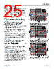
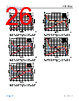
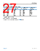
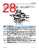
25 / 30 page  Data Sheet ADL5906 THEORY OF OPERATION analog.com Rev. B | 25 of 30 As shown in Figure 54, whereas the slope is stable vs. the tempera- ture at 2140 MHz, the intercept of the ADL5906 does vary slightly vs. temperature (approximately +0.3 dB at +85°C and −0.8 dB at −40°C). This variation in intercept is constant vs. input power level at most frequencies. Table 7 lists the average temperature coeffi- cient of VRMS in mV/°C at frequencies from 100 MHz to 5.8 GHz. This temperature coefficient is given by the following equation: TCVRMS = (DRIFTVRMS/ΔTEMP) × Slope (18) where: DRIFTVRMS is the specified drift of VRMS (scaled in dB) from ambi- ent to either −40°C or +85°C at an input power level of 0 dBm (see Table 1). ∆TEMP is equal to either +65°C for cold drift (that is, +25°C − (−40°C)) or +60°C for hot drift (that is, +85°C − +25°C). Slope is the specified slope of VRMS (see Table 1). For example, at 2.14 GHz, TCVRMS for hot drift can be calculated as TCVRMS = (0.3 dB/60°C) × 56 mV/dB = 0.28 mV/°C The value for slope that is used can also be the slope that is calculated during device calibration. This gives results that are slightly more accurate because there is slight variation in slope from device to device. Table 7 also lists the typical temperature coefficient of the VTEMP temperature sensor output. To calculate the appropriate amount of compensation required at a particular frequency, a VTEMP weighting factor is calculated. This is simply the ratio of the temperature coefficients of VTEMP and VRMS. These weighting factors are also shown in Table 7. Using the data shown in Table 7, an adjusted value for VRMS (VRMS′) can be calculated using the following equation: VRMS′=VRMS− VTEMP−VTEMP25 Weigℎting Factor (19) where: VTEMP25 is equal to the voltage measured on VTEMP during system calibration at ambient temperature. VTEMP is equal to the voltage on VTEMP during normal operation. Figure 55 to Figure 62 show typical plots of VRMS′ vs. input level and temperature at frequencies from 100 MHz to 5.8 GHz when this temperature compensation algorithm is applied. From a system calibration and operation perspective, the only addi- tional measurements that are required to implement this algorithm are measurement and storage of VTEMP during calibration (that is, at ambient temperature) and measurement of VTEMP during opera- tion. All other information required to implement this algorithm (that is, nominal temperature drift of VRMS and temperature coefficient of VTEMP) is based on typical data sheet specifications. Figure 55. VRMS′ and Log Conformance Error vs. Input Level and Temperature at 100 MHz Using VTEMP Intercept Compensation Figure 56. VRMS′ and Log Conformance Error vs. Input Level and Temperature at 700 MHz Using VTEMP Intercept Compensation Figure 57. VRMS′ and Log Conformance Error vs. Input Level and Temperature at 900 MHz Using VTEMP Intercept Compensation |
|
|
链接网址 |
| ALLDATASHEET是否为您带来帮助? [ DONATE ] |
关于 Alldatasheet | 广告服务 | 联系我们 | 隐私政策 | 数据表链接 | 链接交换 | 制造商名单 All Rights Reserved©Alldatasheet.com |
| Russian : Alldatasheetru.com | Korean : Alldatasheet.co.kr | Spanish : Alldatasheet.es | French : Alldatasheet.fr | Italian : Alldatasheetit.com Portuguese : Alldatasheetpt.com | Polish : Alldatasheet.pl | Vietnamese : Alldatasheet.vn Indian : Alldatasheet.in | Mexican : Alldatasheet.com.mx | British : Alldatasheet.co.uk | New Zealand : Alldatasheet.co.nz |
|
Family Site : ic2ic.com |
icmetro.com |
 Chinese ▼
 English
 Chinese
 German
 Japanese
 Russian
 Korean
 Spanish
 French
 Italian
 Portuguese
 Polish
 Vietnamese
 Indian
 Mexican
 British
 New Zealand