|
数据搜索系统,热门电子元器件搜索 |
|
|
数据搜索系统,热门电子元器件搜索 |
|
STDRIVEG611Q 数据表(PDF) 18 Page - STMicroelectronics |
|
|
|||||||||||||||||||||||||||||
STDRIVEG611Q 数据表(HTML) 18 Page - STMicroelectronics |
|
|
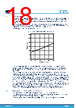
18 / 33 page  6.4.3 Bootstrap diode The STDRIVEG611 integrates a bootstrap diode structure connected between VCC and BOOT pins, to supply the high-side floating supply voltage VBOOT-OUT (or shortly VBO). A very low ESR ceramic capacitor (CBOOT to be selected between 47 nF and 3.3 µF, X7R, 50 V) must be placed as close as possible between the BOOT and OUT pins. The internal bootstrap structure is synchronous with the low-side to reduce the voltage drop between VCC and VBO to almost zero volts. Its turn-on resistance is reported in the electrical characteristics table as RDBOOT. This integrated structure is characterized by a very low recovery charge and current. The bootstrap DC characteristics are detailed in Figure 13. Figure 13. Typical bootstrap diode characteristics 0 100 50 150 200 250 300 Temperature (°C) -50 -10 30 70 110 150 The final voltage drop between VCC and VBO depends on multiple factors like duty cycle, operating frequency, GaN gate charge, GaN leakage, temperature, etc. In case the voltage on VBO is not sufficient for a proper VCCH regulator operation, either increasing the VCC value or using an external bootstrap diode can obtain a correct VBO voltage. Motor control applications typically do not require an external bootstrap diode but it is allowed in case of specific needs as fast high-side start-up or large bootstrap capacitor to allow very long high side turn-on time. It is recommended to place a resistor RBOOT ≥ 2.2 Ω in series with the above mentioned external bootstrap diode to limit the amount of peak charging current. In cases of high side not-zero-current hard switching applications (as motor control), the external bootstrap diode could be subject to high peak current during dead time and peak recovery current at high side turn-on, leading to strong emissions. A higher RBOOT or using the internal bootstrap structure with no recovery current is preferable in these cases. Refer to Section 7.1.1 for further details. Even if a low RBOOT resistor is allowed, it is know that a low value resistor could increase radiated noise; so it is worth properly selecting the CBOOT capacitor based on applicative requirements. With the same start-up time, the smaller CBOOT capacitor the higher RBOOT minimum resistance or even no external diode requirement. Moreover, the internal bootstrap diode has better dynamic characteristics compared to a discrete one. 6.4.4 VHS supply structure and relevant UVLO protection The energy stored in the CBOOT capacitor supplies the input circuitry of the high-side driver. The integrated fast startup VCCH regulator reduces the input VBO voltage to a regulated VHS (VCCH-OUT = 6 V typ.) to drive the gate with a stable and optimized VGS voltage. The fast startup features a minimized wake-up time especially during intermittent operation (burst mode). STDRIVEG611 Device description DS14457 - Rev 2 page 18/33 |
|
链接网址 |
| ALLDATASHEET是否为您带来帮助? [ DONATE ] |
关于 Alldatasheet | 广告服务 | 联系我们 | 隐私政策 | 数据表链接 | 链接交换 | 制造商名单 All Rights Reserved©Alldatasheet.com |
| Russian : Alldatasheetru.com | Korean : Alldatasheet.co.kr | Spanish : Alldatasheet.es | French : Alldatasheet.fr | Italian : Alldatasheetit.com Portuguese : Alldatasheetpt.com | Polish : Alldatasheet.pl | Vietnamese : Alldatasheet.vn Indian : Alldatasheet.in | Mexican : Alldatasheet.com.mx | British : Alldatasheet.co.uk | New Zealand : Alldatasheet.co.nz |
|
Family Site : ic2ic.com |
icmetro.com |
 Chinese ▼
 English
 Chinese
 German
 Japanese
 Russian
 Korean
 Spanish
 French
 Italian
 Portuguese
 Polish
 Vietnamese
 Indian
 Mexican
 British
 New Zealand