|
数据搜索系统,热门电子元器件搜索 |
|
|
数据搜索系统,热门电子元器件搜索 |
|
STDRIVE102BHTR 数据表(PDF) 43 Page - STMicroelectronics |
|
|
|||||||||||||||||||||||||||||
STDRIVE102BHTR 数据表(HTML) 43 Page - STMicroelectronics |
|
|
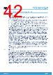
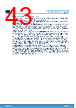
43 / 56 page  7.3 Power supply decoupling capacitors The STDRIVE102BH/H has different supply pins and every pin requires a decoupling capacitor, to be placed as near as possible to the pin. All the capacitors should have a low ESR. A capacitor between the VS pin and the GND (exposed pad) is required for the main supply of the device and to provide a part of the charge pump switching current. A capacitor between VCC and the GND (exposed pad) is required for the supply for the low-side drivers. Its value should be at least 4.7 µF / 25 V to ensure the stability of the VCC when a pulsed current is required by the low- side drivers. Note that, according to the total gate charge of the low-side MOSFET and their switching frequency, the value of this capacitor should be increased. Moreover, an optional 100 nF or smaller capacitor can be added in parallel to filter high frequency noise. A capacitor between the LGC_CAP pin and the GND (exposed pad) is required to filter all the internal rails of the device and avoid any malfunctioning on the internal logic even in case of strong variation on VS supply. Use a 4.7 µF / 16 V capacitor. An optional 100 nF or small capacitor can be added in parallel to filter high frequency noise. A 4.7 µF / 16 V capacitor between VDD and AGND pins is required to ensure stability of the AFE supply. The two capacitors of the charge pump, CFLY between the NCAP and PCAP and CBOOT between VBOOT and VM, must be placed on the same layer of the STDRIVE102BH/H. They must be connected directly to the pins avoiding any via. The rated voltage of CFLY must be compliant with the VM voltage, while CBOOT can be rated 25 V. The values of both capacitors depend on the high-side driver average current, which eventually depends on the total gate charge and the switching frequency of the high-side MOSFETs. The power stage and the motor supply need one or more electrolytic bulk capacitors: their value depends on some parameters mainly related to the current required by the motor and the ripple allowed on the VM supply. In addition, a smaller ceramic capacitor must be added for each half-bridge, to provide the pulsed currents required by the power stage and the gate drivers. Another capacitor must be placed close to the VM pin to filter the switching noise introduced by the charge pump, as reported in Section 7.3. This capacitor should have the same value CBOOT and a voltage rating according to the value of VM. All these capacitors are in parallel and should be referred to the GND power plane described in Section 7.2. STDRIVE102BH, STDRIVE102H Layout recommendations and guidelines DS14545 - Rev 1 page 43/56 |
|
链接网址 |
| ALLDATASHEET是否为您带来帮助? [ DONATE ] |
关于 Alldatasheet | 广告服务 | 联系我们 | 隐私政策 | 数据表链接 | 链接交换 | 制造商名单 All Rights Reserved©Alldatasheet.com |
| Russian : Alldatasheetru.com | Korean : Alldatasheet.co.kr | Spanish : Alldatasheet.es | French : Alldatasheet.fr | Italian : Alldatasheetit.com Portuguese : Alldatasheetpt.com | Polish : Alldatasheet.pl | Vietnamese : Alldatasheet.vn Indian : Alldatasheet.in | Mexican : Alldatasheet.com.mx | British : Alldatasheet.co.uk | New Zealand : Alldatasheet.co.nz |
|
Family Site : ic2ic.com |
icmetro.com |
 Chinese ▼
 English
 Chinese
 German
 Japanese
 Russian
 Korean
 Spanish
 French
 Italian
 Portuguese
 Polish
 Vietnamese
 Indian
 Mexican
 British
 New Zealand