IP101A LF
Data Sheet
Auto MDIX function
IP101A LF will keep sensing incoming signal in MDI RX pair, if no incoming signal is detected, IP101A LF
will switch TX and RX pairs automatically trying to establish connection. IP101A LF supports this function
both in Auto-Negotiation mode and force mode.
LED Configuration
IP101A LF provides 2 LED operation modes,
Mode 1
(default):
25/36
Oct 22, 2007
Copyright © 2004, IC Plus Corp.
IP101A LF-DS-R12
LED
Function
LED0
Link status: Active indicates the link has established
LED1
Duplex operation: Active indicates full duplex
LED2
10BT/ACT: Active indicates 10Mbps connection has established, and blinking while
TX/RX events occur.
LED3
100BT/ACT: Active indicates 100Mbps connection has established, and blinking
while TX/RX events occur.
LED4
Collision detect: Active indicates Collision has occurred
Mode 2
(could be set by pulling up CRS with a 4.7K resistor):
LED
Function
LED0
Link/ACT: Active indicates the link has established, and blinking while TX/RX events
occur.
LED1
Duplex/COL: Active indicates full duplex, and blinking while collision events occur.
LED2
10BT: Active indicates 10Mbps connection has established
LED3
100BT: Active indicates 100Mbps connection has established
LED4
Reserved.
LED pins also include the information of PHY address, the default PHY address is set at 00001b (01h).
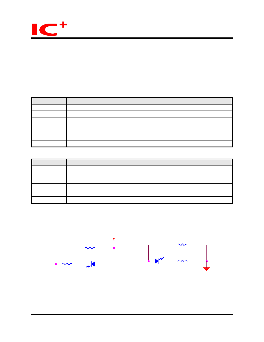
The PHY address can be modified by changing the LED circuitry. The modification can be arranged as
follow:
LEDx {X=0:4}
R26
510 ohm
R27
5.1k ohm
VDD33
D6
LED
R27
5.1k ohm
D6
LED
LEDx {X=0:4}
R26
510 ohm
Figure 3: PHY address Configuration
The left diagram will enable the specific PHY address to 1, if it is connected to VDD33. The diagram on
the right shows the configuration for setting PHY address to 0, when the circuit is connected to ground.
By setting either one of the bits according to the diagram will allow one to modify PHY addresses from
PHYAD0 to PHYAD4.

 Chinese ▼
 English
 Chinese
 German
 Japanese
 Russian
 Korean
 Spanish
 French
 Italian
 Portuguese
 Polish
 Vietnamese
 Indian
 Mexican
 British
 New Zealand