25 / 60 page

IP175A LF
Preliminary Data Sheet
4.5
Fiber port configuration
Each port of IP175A LF can be configured to be a fiber port or a TP port. A port becomes a fiber port if its
FXSDx is connected to a fiber MAU or it is pulled high. A port becomes a TP port if its FXSDx is pulled
low. It is illustrated in the following table.
Port configuration
Voltage on FXSDx
TP port
Fiber port
Fiber signal detect
Condition
< 0.6v
V
--
--
--
> 0.6v, < 1.2v
--
V
Off
Fiber unplugged
> 1.2v
--
V
On
Fiber plugged
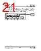
The following is an example that IP175A LF is configured to be 3 TP ports and 2 fiber ports. In this case,
the speed and duplex of fiber ports are defined by pin P0_FORCE100, P0_FORCE_FULL,
P1_FORCE100, and P1_FORCE_FULL.
FXSD1
IP175A LF
Fiber MAU
FXSD0
VCC
FXSD4
FXSD3
FXSD2
Fiber MAU
VCC
25/60
February 20, 2006
Copyright © 2004, IC Plus Corp.
IP175A LF-DS-R08


 Chinese ▼
 English
 Chinese
 German
 Japanese
 Russian
 Korean
 Spanish
 French
 Italian
 Portuguese
 Polish
 Vietnamese
 Indian
 Mexican
 British
 New Zealand