|
数据搜索系统,热门电子元器件搜索 |
|
|
数据搜索系统,热门电子元器件搜索 |
|
AD8318ACPZ-R2 数据表(PDF) 21 Page - Analog Devices |
|
|
|||||||||||||||||||||||||||||
AD8318ACPZ-R2 数据表(HTML) 21 Page - Analog Devices |
|
|
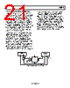
21 / 24 page  AD8318 Rev. B | Page 21 of 24 CHARACTERIZATION SETUP AND METHODS To measure noise spectral density, the 0 Ω resistor in series with the VOUT pin is replaced with a 1 μF dc blocking capacitor. The capacitor is used because the Rohde & Schwarz FSEA spectrum analyzer cannot handle dc voltages at its RF input. The CLPF pin is left open for data collected for Figure 19. For Figure 20, a 1 μF capacitor is placed between CLPF and ground. The large capacitor filters the noise from the detector stages of the log amp. Noise spectral density measurements are taken using the FSEA spectrum analyzer and the SMT06 signal generator. The signal generator frequency is set to 2.2 GHz. The spectrum analyzer has a span of 10 Hz, resolution bandwidth of 50 Hz, video bandwidth of 50 Hz, and averages the signal 100×. Data is adjusted to account for the dc blocking capacitor impedance on the output at lower frequencies. The general hardware configuration used for the AD8318 characterization is shown in Figure 47. The primary setup used for characterization is measurement mode. The characterization board is similar to the customer evaluation board with the exception that the RF input has a Rosenberger SMA connector and R10 has changed to a 1 kΩ resistor to remove cable capacitance from the bench characterization setup. Slope and intercept are calculated in this data sheet and in the production environment using linear regression from −50 dBm to −10 dBm. The slope and intercept generate an ideal line. Log conformance error is the difference from the ideal line and the measured output voltage for a given temperature in dB. For additional information on the error calculation, refer to the Device Calibration and Error Calculation section. The hardware configuration for pulse response measurement replaces the 0 Ω series resistor at the VOUT pin with a 40 Ω resistor; the CLPF pin remains open. Pulse response time is measured using a Tektronix TDS5104 digital phosphor oscilloscope. Both channels on the scope are configured for 50 Ω termination. The 10 Ω internal series resistance at VOUT, combined with the 40 Ω resistor, attenuates the output voltage level by two. RF input frequency is set to 100 MHz with −10 dBm at the input of the device. The RF burst is generated using a Rohde & Schwarz SMT06 with the pulse option with a period of 1.5 μs, a width of 0.1 μs, and a pulse delay of 0.04 μs. The output response is triggered using the video output from the SMT06. Refer to Figure 47 for an overview of the test setup. VIDEO OUT RF OUT –7dBm ROHDE & SCHWARZ SMT06 TEKTRONIX TDS5104 CH1* CH3* TRIGGER VOUT GND 5V AD8318 VPOS VSET INHI INLO 40Ω 52.3Ω 1nF 1nF *50Ω TERMINATION 3dB SPLITTER Figure 47. Pulse Response Measurement Test Setup |
|
|
链接网址 |
| ALLDATASHEET是否为您带来帮助? [ DONATE ] |
关于 Alldatasheet | 广告服务 | 联系我们 | 隐私政策 | 数据表链接 | 链接交换 | 制造商名单 All Rights Reserved©Alldatasheet.com |
| Russian : Alldatasheetru.com | Korean : Alldatasheet.co.kr | Spanish : Alldatasheet.es | French : Alldatasheet.fr | Italian : Alldatasheetit.com Portuguese : Alldatasheetpt.com | Polish : Alldatasheet.pl | Vietnamese : Alldatasheet.vn Indian : Alldatasheet.in | Mexican : Alldatasheet.com.mx | British : Alldatasheet.co.uk | New Zealand : Alldatasheet.co.nz |
|
Family Site : ic2ic.com |
icmetro.com |
 Chinese ▼
 English
 Chinese
 German
 Japanese
 Russian
 Korean
 Spanish
 French
 Italian
 Portuguese
 Polish
 Vietnamese
 Indian
 Mexican
 British
 New Zealand