|
数据搜索系统,热门电子元器件搜索 |
|
|
数据搜索系统,热门电子元器件搜索 |
|
TNETE2004 数据表(PDF) 24 Page - Texas Instruments |
|
|
|||||||||||||||||||||||||||||
TNETE2004 数据表(HTML) 24 Page - Texas Instruments |
|
|
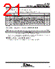
24 / 46 page  TNETE2004 MDIO-MANAGED QuadPHY FOUR 10BASE-T PHYSICAL-LAYER INTERFACES SPWS023D – OCTOBER 1996 – REVISED OCTOBER 1997 24 POST OFFICE BOX 655303 • DALLAS, TEXAS 75265 TNETE2004 all-PHY control register – QuadPHY_4ctl at 0x13 BYTE 1 15 14 13 12 11 10 9 8 7 6 5 4 3 2 1 BYTE 0 0 L O O P B A C K 3 L O O P B A C K 2 L O O P B A C K 1 L O O P B A C K 0 P D O W N 3 P D O W N 2 P D O W N 1 P D O W N 0 I S O L A T E 3 I S O L A T E 2 I S O L A T E 1 I S O L A T E 0 D U P L E X 3 D U P L E X 2 D U P L E X 1 D U P L E X 0 Figure 14. TNETE2004 All-PHY Control Register – QuadPHY_4ctl at 0x13 Table 10. TNETE2004 All-PHY Control Register (QuadPHY_4ctl at 0x13) Bit Functions BIT FUNCTION DIRECTION† NO. NAME FUNCTION DIRECTION† 15 LOOPBACK3 Loopback mode. Writing a 1 to LOOPBACK3 sets PHY3 into loopback mode. R/W 14 LOOPBACK2 Loopback mode. Writing a 1 to LOOPBACK2 sets PHY2 into loopback mode. R/W 13 LOOPBACK1 Loopback mode. Writing a 1 to LOOPBACK1 sets PHY1 into loopback mode. R/W 12 LOOPBACK0 Loopback mode. Writing a 1 to LOOPBACK0 sets PHY0 into loopback mode. R/W 11 PDOWN3 Power-down mode. When set, PDOWN3 places PHY3 in a power-down mode. In this mode, it is not possible to receive or transmit data. See Note 1. R/W 10 PDOWN2 Power-down mode. When set, PDOWN2 places PHY2 in a power-down mode. In this mode, it is not possible to receive or transmit data. See Note 1. R/W 9 PDOWN1 Power-down mode. When set, PDOWN1 places PHY1 in a power-down mode. In this mode, it is not possible to receive or transmit data. See Note 1. R/W 8 PDOWN0 Power-down mode. When set, PDOWN0 places PHY0 in a power-down mode. In this mode, it is not possible to receive or transmit data. See Note 1. R/W 7 ISOLATE3 PHY pin isolation. When set, PHY3 electrically isolates itself from the pins. In this state, it does not respond to TXD or TXEN and presents a high impedance on RXD, RXCLK, and COL. It still responds to MII data frames, however. R/W 6 ISOLATE2 PHY pin isolation. When set, PHY2 electrically isolates itself from the pins. In this state, it does not respond to TXD or TXEN and presents a high impedance on RXD, RXCLK, and COL. It still responds to MII data frames, however. R/W 5 ISOLATE1 PHY pin isolation. When set, PHY1 electrically isolates itself from the pins. In this state, it does not respond to TXD or TXEN and presents a high impedance on RXD, RXCLK, and COL. It still responds to MII data frames, however. R/W 4 ISOLATE0 PHY pin isolation. When set, PHY0 electrically isolates itself from the pins. In this state, it does not respond to TXD or TXEN and presents a high impedance on RXD, RXCLK, and COL. It still responds to MII data frames, however. R/W 3 DUPLEX3 Set full-duplex mode. Setting DUPLEX3 forces PHY3 into full-duplex mode. Resetting forces half-duplex mode. R/W 2 DUPLEX2 Set full-duplex mode. Setting DUPLEX2 forces PHY2 into full-duplex mode. Resetting forces half-duplex mode. R/W 1 DUPLEX1 Set full-duplex mode. Setting DUPLEX1 forces PHY1 into full-duplex mode. Resetting forces half-duplex mode. R/W 0 DUPLEX0 Set full-duplex mode. Setting DUPLEX0 forces PHY0 into full-duplex mode. Resetting forces half-duplex mode. R/W † R/W = read/write NOTE 1. If all four PHYs are in power-down mode simultaneously, then reset must be used to power up the device. It is not possible to power up an individual PHY if all four PHYs are in power-down mode. |
|
链接网址 |
| ALLDATASHEET是否为您带来帮助? [ DONATE ] |
关于 Alldatasheet | 广告服务 | 联系我们 | 隐私政策 | 数据表链接 | 链接交换 | 制造商名单 All Rights Reserved©Alldatasheet.com |
| Russian : Alldatasheetru.com | Korean : Alldatasheet.co.kr | Spanish : Alldatasheet.es | French : Alldatasheet.fr | Italian : Alldatasheetit.com Portuguese : Alldatasheetpt.com | Polish : Alldatasheet.pl | Vietnamese : Alldatasheet.vn Indian : Alldatasheet.in | Mexican : Alldatasheet.com.mx | British : Alldatasheet.co.uk | New Zealand : Alldatasheet.co.nz |
|
Family Site : ic2ic.com |
icmetro.com |
 Chinese ▼
 English
 Chinese
 German
 Japanese
 Russian
 Korean
 Spanish
 French
 Italian
 Portuguese
 Polish
 Vietnamese
 Indian
 Mexican
 British
 New Zealand