|
数据搜索系统,热门电子元器件搜索 |
|
|
数据搜索系统,热门电子元器件搜索 |
|
SSM2804CBZ-R7 数据表(PDF) 15 Page - Analog Devices |
|
|
|||||||||||||||||||||||||||||
SSM2804CBZ-R7 数据表(HTML) 15 Page - Analog Devices |
|
|
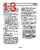
15 / 36 page  SSM2804 Rev. 0 | Page 15 of 36 ALC Compression and Limiter Modes The ALC implemented on the SSM2804 has two operation modes: compression mode and limiter mode. When the ALC is triggered for medium-level input signals, the ALC is in com- pression mode. In this mode, an increase of the output signal is one-third the increase of the input signal. For example, if the input signal increases by 3 dB, the ALC reduces the amplifier gain by 2 dB and, thus, the output signal increases by only 1 dB. As the input signal becomes very large, the ALC transitions to limiter mode. In this mode, the output stays at a given threshold level, VTH, even if the input signal grows larger. As an example of limiter mode operation, when a large input signal increases by 3 dB, the ALC reduces the amplifier gain by 3 dB and, thus, the output increases by 0 dB. When the amplifier gain is reduced to 1 dB, the ALC cannot reduce the gain further, and the output increases again. This is because the total range of the ALC opera- tion has bottomed out due to extreme input voltage at high gain. To avoid potential speaker damage, the maximum input amplitude should not be large enough to exceed the maximum attenuation (to a level of 1 dB) of the limiter mode. Attack Time, Hold Time, and Release Time When the amplifier input signal exceeds a preset threshold, the ALC reduces amplifier gain rapidly until the output voltage settles to a target level. This target level is maintained for a certain period. If the input voltage does not exceed the threshold again, the ALC increases the gain gradually. The attack time is the time taken to reduce the gain from maxi- mum to minimum. The hold time is the time that the reduced gain is maintained. The release time is the time taken to increase the gain from minimum to maximum. These times are shown in Table 8. The attack time and the release time can be set using the ALC 1 control register (Address 0x0A). Table 8. ALC Attack, Hold, and Release Times Time1 Duration Attack Time 32 μs to 4 ms (per 0.5 dB step) Hold Time 90 ms to 120 ms Release Time 4 ms to 512 ms (per 0.5 dB step) 1 The attack time and release time can be adjusted using the I2C interface. The hold time cannot be adjusted. Soft-Knee Compression Often performed using sophisticated DSP algorithms, soft-knee compression provides maximum sound quality with effective speaker protection. Instead of using a fixed compression setting prior to limiting, the SSM2804 allows for a much more subtle transition into limiting mode, preserving the original sound quality of the source audio. Figure 31 to Figure 33 show the various soft-knee compression settings that can be selected using the COMP bit settings (Bits[D6:D5] of Register 0x0B). 0 0.5 1.0 1.5 2.0 2.5 0 0.05 0.10 0.15 0.20 0.30 0.35 0.40 0.45 0.25 0.50 INPUT VOLTAGE (V) 00 (COMPRESSION MODE 1) 01 (COMPRESSION MODE 2) 10 (COMPRESSION MODE 3) 11 (LIMITER MODE) 2.7V × 0.78 = 2.106V Figure 31. Adjustable Compression Settings, PVDD = 2.7 V, ALC Threshold Level = 78% 0 0.5 1.5 2.0 2.5 1.0 3.0 3.5 0 0.1 0.2 0.3 0.4 0.6 0.7 0.8 0.9 0.5 1.0 INPUT VOLTAGE (V) 00 (COMPRESSION MODE 1) 01 (COMPRESSION MODE 2) 10 (COMPRESSION MODE 3) 11 (LIMITER MODE) 3.6V × 0.78 = 2.808V Figure 32. Adjustable Compression Settings, PVDD = 3.6 V, ALC Threshold Level = 78% 0 0.5 1.5 2.0 2.5 1.0 3.0 4.0 3.5 4.5 0 0.2 0.4 0.6 0.8 1.2 1.4 1.6 1.8 1.0 2.0 INPUT VOLTAGE (V) 00 (COMPRESSION MODE 1) 01 (COMPRESSION MODE 2) 10 (COMPRESSION MODE 3) 11 (LIMITER MODE) 5.0V × 0.78 = 3.9V Figure 33. Adjustable Compression Settings, PVDD = 5.0 V, ALC Threshold Level = 78% |
|
链接网址 |
| ALLDATASHEET是否为您带来帮助? [ DONATE ] |
关于 Alldatasheet | 广告服务 | 联系我们 | 隐私政策 | 数据表链接 | 链接交换 | 制造商名单 All Rights Reserved©Alldatasheet.com |
| Russian : Alldatasheetru.com | Korean : Alldatasheet.co.kr | Spanish : Alldatasheet.es | French : Alldatasheet.fr | Italian : Alldatasheetit.com Portuguese : Alldatasheetpt.com | Polish : Alldatasheet.pl | Vietnamese : Alldatasheet.vn Indian : Alldatasheet.in | Mexican : Alldatasheet.com.mx | British : Alldatasheet.co.uk | New Zealand : Alldatasheet.co.nz |
|
Family Site : ic2ic.com |
icmetro.com |
 Chinese ▼
 English
 Chinese
 German
 Japanese
 Russian
 Korean
 Spanish
 French
 Italian
 Portuguese
 Polish
 Vietnamese
 Indian
 Mexican
 British
 New Zealand