|
数据搜索系统,热门电子元器件搜索 |
|
|
数据搜索系统,热门电子元器件搜索 |
|
AD8606ARM-R2 数据表(PDF) 14 Page - Analog Devices |
|
|
|||||||||||||||||||||||||||||
AD8606ARM-R2 数据表(HTML) 14 Page - Analog Devices |
|
|
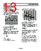
14 / 20 page  AD8605/AD8606/AD8608 Rev. D | Page 14 of 20 FREQUENCY (Hz) 0.1 0.01 0.0001 20 20k 100 1k 0.001 10k VSY = 2.5V AV = 1 BW = 22kHz Figure 45. THD + N TOTAL NOISE INCLUDING SOURCE RESISTORS The low input current noise and input bias current of the AD8605 make it the ideal amplifier for circuits with substantial input source resistance such as photodiodes. Input offset voltage increases by less than 0.5 nV per 1 kΩ of source resistance at room temperature and increases to 10 nV at 85°C. The total noise density of the circuit is () S S n n TOTAL n TR k R i e e 4 2 2 , + + = where: en is the input voltage noise density of the AD8605 in is the input current noise density of the AD8605 RS is the source resistance at the noninverting terminal k is Boltzmann’s constant (1.38 × 10⁻²³ J/K) T is the ambient temperature in Kelvin (T = 273 + °C) For example, with RS = 10 kΩ, the total voltage noise density is roughly 15 nV/√Hz. For RS < 3.9 kΩ, en dominates and en,TOTAL ≈ en. The current noise of the AD8605 is so low that its total density does not become a significant term unless RS is greater than 6 MΩ. The total equivalent rms noise over a specific bandwidth is expressed as ( ) BW e E TOTAL n n , = where BW is the bandwidth in hertz. Note that the analysis above is valid for frequencies greater than 100 Hz and assumes relatively flat noise, above 10 kHz. For lower frequencies, flicker noise (1/f) must be considered. CHANNEL SEPARATION Channel separation, or inverse crosstalk, is a measure of the signal feed from one amplifier (channel) to an other on the same IC. The AD8606 has a channel separation of greater than −160 dB up to frequencies of 1 MHz, allowing the two amplifiers to amplify ac signals independently in most applications. FREQUENCY (Hz) 10M 1M 100k 10k 1k 100 100M –20 0 –40 –60 –80 –100 –120 –140 –160 –180 Figure 46. Channel Separation vs. Frequency CAPACITIVE LOAD DRIVE The AD8605 can drive large capacitive loads without oscillation. Figure 47 shows the output of the AD8606 in response to a 200 mV input signal. In this case, the amplifier was configured in positive unity gain, worst case for stability, while driving a 1,000 pF load at its output. Driving larger capacitive loads in unity gain may require the use of additional circuitry. TIME (10 µs/DIV) VS = ±2.5V AV = 1 RL = 10kΩ CL = 1 Figure 47. Capacitive Load Drive without Snubber A snubber network, shown in Figure 48, helps reduce the signal overshoot to a minimum and maintain stability. Although this circuit does not recover the loss of bandwidth induced by large capacitive loads, it greatly reduces the overshoot and ringing. This method does not reduce the maximum output swing of the amplifier. Figure 49 shows a scope photograph of the output at the snubber circuit. The overshoot is reduced from over 70% to less than 5%, and the ringing is eliminated by the snubber. Optimum values for RS and CS are determined experimentally. |
|
|
链接网址 |
| ALLDATASHEET是否为您带来帮助? [ DONATE ] |
关于 Alldatasheet | 广告服务 | 联系我们 | 隐私政策 | 数据表链接 | 链接交换 | 制造商名单 All Rights Reserved©Alldatasheet.com |
| Russian : Alldatasheetru.com | Korean : Alldatasheet.co.kr | Spanish : Alldatasheet.es | French : Alldatasheet.fr | Italian : Alldatasheetit.com Portuguese : Alldatasheetpt.com | Polish : Alldatasheet.pl | Vietnamese : Alldatasheet.vn Indian : Alldatasheet.in | Mexican : Alldatasheet.com.mx | British : Alldatasheet.co.uk | New Zealand : Alldatasheet.co.nz |
|
Family Site : ic2ic.com |
icmetro.com |
 Chinese ▼
 English
 Chinese
 German
 Japanese
 Russian
 Korean
 Spanish
 French
 Italian
 Portuguese
 Polish
 Vietnamese
 Indian
 Mexican
 British
 New Zealand