|
数据搜索系统,热门电子元器件搜索 |
|
|
数据搜索系统,热门电子元器件搜索 |
|
AD9042ST/PCB 数据表(PDF) 11 Page - Analog Devices |
|
|
|||||||||||||||||||||||||||||
AD9042ST/PCB 数据表(HTML) 11 Page - Analog Devices |
|
|
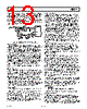
11 / 24 page  AD9042 REV. A –11– THEORY OF OPERATION The AD9042 analog-to-digital converter (ADC) employs a two- stage subrange architecture. This design approach ensures 12-bit accuracy, without the need for laser trim, at low power. As shown in the functional block diagram, the 1 V p-p single- ended analog input, centered at 2.4 V, drives a single-in to differential-out amplifier, A1. The output of A1 drives the first track-and-hold, TH1. The high state of the ENCODE pulse places TH1 in hold mode. The held value of TH1 is applied to the input of the 6-bit coarse ADC. The digital output of the coarse ADC drives a 6-bit DAC; the DAC is 12 bits accurate. The output of the 6-bit DAC is subtracted from the delayed analog signal at the input to TH3 to generate a residue signal. TH2 is used as an analog pipeline to null out the digital delay of the coarse ADC. The residue signal is passed to TH3 on a subsequent clock cycle where the signal is amplified by the residue amplifier, A2, and converted to a digital word by the 7-bit residue ADC. One bit of overlap is used to accommodate any linearity errors in the coarse ADC. The 6-bit coarse ADC word and 7-bit residue word are added together and corrected in the digital error correction logic to generate the output word. The result is a 12-bit parallel digital word which is CMOS-compatible, coded as twos complement. APPLYING THE AD9042 Encoding the AD9042 The AD9042 is designed to interface with TTL and CMOS logic families. The source used to drive the ENCODE pin(s) must be clean and free from jitter. Sources with excessive jitter will limit SNR (ref. Equation 1 under “Noise Floor and SNR”). 0.01µF TTL OR CMOS SOURCE ENCODE ENCODE AD9042 Figure 26. Single-Ended TTL /CMOS Encode The AD9042 encode inputs are connected to a differential input stage (see Figure 3 under EQUIVALENT CIRCUITS). With no input connected to either the ENCODE or input, the voltage dividers bias the inputs to 1.6 volts. For TTL or CMOS usage, the encode source should be connected to ENCODE. ENCODE should be decoupled using a low inductance or microwave chip capacitor to ground. Devices such as AVX 05085C103MA15, a 0.01 µF capacitor, work well. If a logic threshold other than the nominal 1.6 V is required, the following equations show how to use an external resistor, RX, to raise or lower the trip point (see Figure 3; R1 = 17k, R2 = 8k). V 1 = 5R 2RX R 1R2 + R1RX + R2RX to lower logic threshold. 0.01µF ENCODE SOURCE ENCODE ENCODE AD9042 RX Vl +5V R1 R2 Figure 27. Lower Logic Threshold for Encode V 1 = 5R 2 R 2 + R 1RX R 1 + RX to raise logic threshold. 0.01µF ENCODE SOURCE ENCODE ENCODE AD9042 RX Vl +5V R1 R2 AVCC Figure 28. Raise Logic Threshold for Encode While the single-ended encode will work well for many applications, driving the encode differentially will provide increased performance. Depending on circuit layout and system noise, a 1 dB to 3 dB improvement in SNR can be realized. It is not recommended that differential TTL logic be used however, because most TTL families that support complementary outputs are not delay or slew rate matched. Instead, it is recommended that the encode signal be ac-coupled into the ENCODE and ENCODE pins. The simplest option is shown below. The low jitter TTL signal is coupled with a limiting resistor, typically 100 ohms, to the primary side of an RF transformer (these transformers are inexpensive and readily available; part# in Figure 29 is from Mini-Circuits). The secondary side is connected to the ENCODE and ENCODE pins of the converter. Since both encode inputs are self biased, no additional components are required. TTL ENCODE ENCODE AD9042 100 Ω T1-1T Figure 29. TTL Source – Differential Encode |
|
|
链接网址 |
| ALLDATASHEET是否为您带来帮助? [ DONATE ] |
关于 Alldatasheet | 广告服务 | 联系我们 | 隐私政策 | 数据表链接 | 链接交换 | 制造商名单 All Rights Reserved©Alldatasheet.com |
| Russian : Alldatasheetru.com | Korean : Alldatasheet.co.kr | Spanish : Alldatasheet.es | French : Alldatasheet.fr | Italian : Alldatasheetit.com Portuguese : Alldatasheetpt.com | Polish : Alldatasheet.pl | Vietnamese : Alldatasheet.vn Indian : Alldatasheet.in | Mexican : Alldatasheet.com.mx | British : Alldatasheet.co.uk | New Zealand : Alldatasheet.co.nz |
|
Family Site : ic2ic.com |
icmetro.com |
 Chinese ▼
 English
 Chinese
 German
 Japanese
 Russian
 Korean
 Spanish
 French
 Italian
 Portuguese
 Polish
 Vietnamese
 Indian
 Mexican
 British
 New Zealand