|
数据搜索系统,热门电子元器件搜索 |
|
|
数据搜索系统,热门电子元器件搜索 |
|
24AA02UID 数据表(PDF) 8 Page - Microchip Technology |
|
|
|||||||||||||||||||||||||||||
24AA02UID 数据表(HTML) 8 Page - Microchip Technology |
|
|
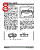
8 / 30 page  24AA02UID/24AA025UID DS20005202A-page 8 2013 Microchip Technology Inc. 5.0 DEVICE ADDRESSING A control byte is the first byte received following the Start condition from the master device. The control byte consists of a 4-bit control code. For the 24AA02XUID, this is set as ‘ 1010’ binary for read and write operations. For the 24AA02UID the next three bits of the control byte are “don’t cares”. For the 24AA025UID, the next three bits of the control byte are the Chip Select bits (A2, A1, A0). The Chip Select bits allow the use of up to eight 24AA025UID devices on the same bus and are used to select which device is accessed. The Chip Select bits in the control byte must correspond to the logic levels on the corre- sponding A2, A1 and A0 pins for the device to respond. These bits are in effect the three Most Significant bits of the word address. For the 6-pin SOT-23 package, the A2 address pin is not available. During device addressing, the A2 Chip Select bit should be set to ‘0’. The last bit of the control byte defines the operation to be performed. When set to ‘ 1’, a read operation is selected. When set to ‘ 0’, a write operation is selected. Following the Start condition, the 24AA02XUID moni- tors the SDA bus, checking the device type identifier being transmitted and, upon a ‘1010’ code, the slave device outputs an Acknowledge signal on the SDA line. Depending on the state of the R/W bit, the 24AA02XUID will select a read or write operation. FIGURE 5-1: CONTROL BYTE ALLOCATION 5.1 Contiguous Addressing Across Multiple Devices The Chip Select bits A2, A1 and A0 can be used to expand the contiguous address space for up to 16K bits by adding up to eight 24AA025UID devices on the same bus. In this case, software can use A0 of the con- trol byte as address bit A8, A1 as address bit A9 and A2 as address bit A10. It is not possible to sequentially read across device boundaries. For the SOT-23 package, up to four 24AA025UID devices can be added for up to 8K bits of address space. In this case, software can use A0 of the control byte as address bit A8, and A1 as address bit A9. It is not possible to sequentially read across device boundaries. FIGURE 5-2: ADDRESS SEQUENCE BIT ASSIGNMENTS Operation Control Code Chip Select R/W Read 1010 Chip Address 1 Write 1010 Chip Address 0 10 1 0 A2* A1* A0* R/W ACK Start Bit Read/Write Bit S Slave Address Acknowledge Bit Control Code Chip Select Bits Note: * Bits A0, A1 and A2 are “don’t cares” for the 24AA02UID. 1 010 R/W A 7 A 0 •• • • • • Control Byte Address Low Byte Control Code Chip Select bits Note: * Bits A0, A1 and A2 are “don’t cares” for the 24AA02UID. A2* A1* A0* |
|
|
链接网址 |
| ALLDATASHEET是否为您带来帮助? [ DONATE ] |
关于 Alldatasheet | 广告服务 | 联系我们 | 隐私政策 | 数据表链接 | 链接交换 | 制造商名单 All Rights Reserved©Alldatasheet.com |
| Russian : Alldatasheetru.com | Korean : Alldatasheet.co.kr | Spanish : Alldatasheet.es | French : Alldatasheet.fr | Italian : Alldatasheetit.com Portuguese : Alldatasheetpt.com | Polish : Alldatasheet.pl | Vietnamese : Alldatasheet.vn Indian : Alldatasheet.in | Mexican : Alldatasheet.com.mx | British : Alldatasheet.co.uk | New Zealand : Alldatasheet.co.nz |
|
Family Site : ic2ic.com |
icmetro.com |
 Chinese ▼
 English
 Chinese
 German
 Japanese
 Russian
 Korean
 Spanish
 French
 Italian
 Portuguese
 Polish
 Vietnamese
 Indian
 Mexican
 British
 New Zealand