|
数据搜索系统,热门电子元器件搜索 |
|
|
数据搜索系统,热门电子元器件搜索 |
|
ICS200 数据表(PDF) 12 Page - Integrated Circuit Systems |
|
|
|||||||||||||||||||||||||||||
ICS200 数据表(HTML) 12 Page - Integrated Circuit Systems |
|
|
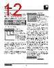
12 / 21 page  ICS2008B 12 ICS2008B Rev D 4/05/05 UART Registers The UART emulates a 6850. Since the UART is tailored to MIDI applications, some of the generic 6850 functions have been omitted. The registers described below reflect that. The two UART registers, Command/Status and Data, are accessible to the processor as shown in the following map. UART Command/Status Register Bit Rate — This field selects the bit rate for data transmit and receive. After a master reset, its value is 11. One of the three bit rates must be selected in order to start the UART’s operation. Writing a 11 will reset the UART. TC1, TC0 — Bits 6 and 5, Transmit Control, provide control for transmit interrupt (when TBE is true), RTS control, and transmit BREAK level. RIE — Bit 7, Receive interrupt enable, when set to one, enables the UART to interrupt the processor when the receive buffer is full or a receive overrun has occurred. RBF — Bit 0, Receive Buffer Full, is set to 1 when read data is available in the UART data register. It is cleared to 0 when the UART data register is read. TBE — Bit 1, Transmit Buffer Empty, is cleared to 0 when data is written to the UART data register. It is set to 1 when the UART transfers that data to its output shift register. CTS — Bit 3, Clear-to-Send, is an active low status bit indicating the state of the CTS* input pin. A 0 in this bit position indicates that the modem or receiving device is ready to receive characters. A 1 indicates not ready. When CTS is inactive, 1, TBE is held at 0, the not-empty state. FE — Bit 4, Framing Error, when set to 1, indicates that the receive character was improperly framed by the start and stop bits. It is detected by the absence of the first stop bit. This indicator is valid as long as the character data is valid. OV — Bit 5, Receiver Overrun, is an error flag indicating that one or more characters in the data stream has been lost. It is set to 1 when a new character overwrites an old character which has not been read. The overrun error is cleared to 0 when a character is read from the UART data register. IRQ — Bit 7, Interrupt Request, is a status bit which reflects the state of the interrupt request from the UART to the processor. When IRQ is 1, an interrupt is pending. Otherwise, no interrupt is pending. The UART data register is actually two registers, a transmit buffer and a receive buffer. Writing to the data register causes the transmit buffer to be written. Reading from the data regis- ter causes the receive buffer to be read. UARTCS* A1 A0 REGISTER 0 X 0 UART Command/Status Register 0X 1 UART Data Register UART Command Register Bit Rate (00 - 9600, 10 - 38.4K) (01 - 31.25K, 11 - Reset) Reserved TC1, TC0 Transmit Control 00 - RTS* – low, Tx IRQ disabled 01 - RTS* – low, Tx IRQ enabled 10 - RTS* – high, Tx IRQ disabled 11 - RTS* – low, Transmit BREAK, Tx IRQ disabled RIE - Receive Interrupt Enable UART0 (write) 7 6 5 4 3 2 1 0 UART2 Status Register RBF – Receive Buffer Full (1-Full) TBE – Transmit Buffer Empty (1-Empty) Reserved CTS – Clear-to-Send (0-Active) FE – Framing Error (1-Error) OV – Receiver Overrun (1-Overrun) Reserved IRQ – Interrupt Request (1-Active) UART0 (read) UART Data Register UART1 7 6 5 4 3 2 1 0 7 6 5 4 3 2 1 0 |
|
|
链接网址 |
| ALLDATASHEET是否为您带来帮助? [ DONATE ] |
关于 Alldatasheet | 广告服务 | 联系我们 | 隐私政策 | 数据表链接 | 链接交换 | 制造商名单 All Rights Reserved©Alldatasheet.com |
| Russian : Alldatasheetru.com | Korean : Alldatasheet.co.kr | Spanish : Alldatasheet.es | French : Alldatasheet.fr | Italian : Alldatasheetit.com Portuguese : Alldatasheetpt.com | Polish : Alldatasheet.pl | Vietnamese : Alldatasheet.vn Indian : Alldatasheet.in | Mexican : Alldatasheet.com.mx | British : Alldatasheet.co.uk | New Zealand : Alldatasheet.co.nz |
|
Family Site : ic2ic.com |
icmetro.com |
 Chinese ▼
 English
 Chinese
 German
 Japanese
 Russian
 Korean
 Spanish
 French
 Italian
 Portuguese
 Polish
 Vietnamese
 Indian
 Mexican
 British
 New Zealand