|
数据搜索系统,热门电子元器件搜索 |
|
|
数据搜索系统,热门电子元器件搜索 |
|
ICS200 数据表(PDF) 15 Page - Integrated Circuit Systems |
|
|
|||||||||||||||||||||||||||||
ICS200 数据表(HTML) 15 Page - Integrated Circuit Systems |
|
|
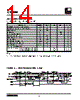
15 / 21 page  15 ICS2008B ICS2008B Rev D 4/05/05 Applications Crystal Oscillator This oscillator will operate properly with either a serial or parallel resonant crystal. If fre- quency accuracy is critical, a parallel resonant crystal is recommended. Threshold Bypass Pins These pins provide access to the internal references for clamp level (CTHRESH), SYNC slicer (STHRESH), and data slicer (DTHRESH). In general, these pins are left open, and the levels are output. However, should the user want to set other levels, these pins can be over-driven with the desired threshold level(s). CTHRESH is the threshold to which the input video sync tips are clamped. The CTHRESH level is nomi- nally 1.3V. With the incoming video riding on this 1.3V DC level, the in- ternal SYNC separator sizes the video at 20 IRE up from the SYNC tips. This level, STHRESH, is nomi- nally 0.14V above CTHRESH. The SYNC separator ignores short pulses which fall below the STHRESH level such as these that come from the chroma component of the video. DTHRESH is the data slicer reference. It is nominally 0.57V above CTHRESH. Video Inputs Y1, Y2, C1 and C2 pins must be capacitively coupled to the terminated video source(s). These in- puts are clamped to the CTHRESH level. A typi- cal coupling capacitance is 0.1 µF. Video Outputs YOUT and COUT are outputs of analog multi- plexers which select the video source from Y1, C1 or Y2, C2. These outputs are not buffered, so minimizes signal dis- tortion. It is, therefore, important to keep the ca- pacitive and resistive load on the YOUT and COUT pins to a mini- mum. If DC coupling is desired, the plus input of the opamp should be high impedance with a low bias current, and its out- put should be able to drive a 75 ohm load with an appropriate video bandwidth. In general, composite NTSC and S-video signals have a bandwidth of 4.2 MHz. A minimum output buffer bandwidth of 10 MHz is recommended. Care should be taken in board layout to minimize stray capacitance on the YOUT and COUT pins. Otherwise, there could be high fre- quency roll-off which could result in a loss of chrominance amplitude. Self Biased Inputs The CLICK and FRAME inputs are biased to 1/2 VDD and connected to plus inputs of two comparators. The minus inputs are internally biased to 1/2 VDD. When CLICK or FRAME sources are ana- log, they should be capacitively coupled to the input pin. However, if the sources are digital, they may be tied to the pins di- rectly. It is important to make sure that the digital levels into these pins swing above and below the 1/2 VDD threshold of the com- parators. This is not a problem with digital CMOS sources, but it could be with TTL sources. LTCIN + and LTCIN – are comparator inputs for the LTC input. This differential input is provided to maximize noise immunity. If the LTC source is single ended, the LTCIN – should be capacitively coupled to the ground reference of that source. If the LTC source is digital, set the LTCIN – to the desired threshold, and connect the digital source to LTCIN+. Fig. 4 - Crystal Oscillator Fig. 5 –Threshold Bias Fig. 6 – S-Video Input Fig. 7 -Video Output Fig. 8 - Self Biased Inputs |
|
|
链接网址 |
| ALLDATASHEET是否为您带来帮助? [ DONATE ] |
关于 Alldatasheet | 广告服务 | 联系我们 | 隐私政策 | 数据表链接 | 链接交换 | 制造商名单 All Rights Reserved©Alldatasheet.com |
| Russian : Alldatasheetru.com | Korean : Alldatasheet.co.kr | Spanish : Alldatasheet.es | French : Alldatasheet.fr | Italian : Alldatasheetit.com Portuguese : Alldatasheetpt.com | Polish : Alldatasheet.pl | Vietnamese : Alldatasheet.vn Indian : Alldatasheet.in | Mexican : Alldatasheet.com.mx | British : Alldatasheet.co.uk | New Zealand : Alldatasheet.co.nz |
|
Family Site : ic2ic.com |
icmetro.com |
 Chinese ▼
 English
 Chinese
 German
 Japanese
 Russian
 Korean
 Spanish
 French
 Italian
 Portuguese
 Polish
 Vietnamese
 Indian
 Mexican
 British
 New Zealand