|
数据搜索系统,热门电子元器件搜索 |
|
|
数据搜索系统,热门电子元器件搜索 |
|
P9242-R 数据表(PDF) 14 Page - Integrated Device Technology |
|
|
|||||||||||||||||||||||||||||
P9242-R 数据表(HTML) 14 Page - Integrated Device Technology |
|
|
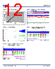
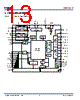
14 / 31 page  P9242-R Datasheet © 2016 Integrated Device Technology, Inc 14 December 16, 2016 7. Theory of Operation A wireless power charging system has a base station with one or more transmitters that make power available via DC-to-AC inverter(s) and transmit the power over a strongly-coupled inductor pair to a receiver in a mobile device. The amount of power transferred to the mobile device is controlled by the wireless power receiver by sending communication packets to the transmitter to increase, decrease, or maintain the power level. The communication from receiver to transmitter is purely digital and consists of 1’s and 0’s that ride on top of the power link that exists between the transmitter (TX) and receiver (RX) coil. Communication from transmitter to receiver is achieved by frequency shift keying (FSK) modulation over the power signal frequency and amplitude shift keying (ASK) is used for the communication protocol from receiver to transmitter. A feature of the wireless charging system is the fact that when it is not delivering power, the transmitter is in Standby Mode. The transmitter remains in Standby Mode and periodically pings until it detects the presence of a receiver. Once an Extended Power Profile Receiver is detected, such as the P9221-R or equivalent, the transmitter will provide with up to 15W of output power. If a Baseline Power Profile Receiver is present, the transmitter will deliver only up to 5W of output power. The P9242-R contains features that ensure a high level of functionality and compliance with the WPC requirements, such as a power path that efficiently achieves power transfer, a simple and robust communication demodulation circuit, safety and protection circuits, configuration, and status indication circuits. 7.1 Over-Current Limit – ILIM The over-current protection (OCP) is designed to protect the half-bridge and wireless receiver unit from becoming exposed to operating conditions that could potentially cause damage or unexpected behavior from the system. The input current is continuously monitored during the power transfer stage. If the input current goes above the OCP threshold of 2.1A (typical), the P9242-R will increase the switching frequency or reduce the duty cycle in order to keep the input current below the OCP value. 7.2 Enable Pin – EN ̅̅̅̅̅ The P9242-R can be disabled by applying a logic HIGH to the EN pin. When the voltage on the EN pin is pulled high, operation is suspended and the P9242-R is placed in the low-current Shut Down Mode. If pulled low, the P9242-R is active. 7.3 Buzzer – BUZR An optional AC-type ceramic buzzer can be connected between the BUZR pin to GND through a current limiting resistor. A short 4kHz “chirp” sound will indicate when the object is detected. Do not connect this pin if the buzzer function is not desired. 7.4 Voltage Demodulation – VDEM1 In order to increase the communication reliability in any load condition, the P9242-R has integrated two demodulation schemes, one based on coil current information and the other based on coil voltage modulation. The voltage mode envelope detector is implemented using a discrete solution as depicted on Figure 14. This simple implementation achieves the envelope detector function low-pass filter as well as the DC filter function. Figure 14. Voltage Mode Envelope Detector D1 R1 R2 C1 R3 C2 C3 Packet Decoder To Registers P9242-R VDEM1 |
|
链接网址 |
| ALLDATASHEET是否为您带来帮助? [ DONATE ] |
关于 Alldatasheet | 广告服务 | 联系我们 | 隐私政策 | 数据表链接 | 链接交换 | 制造商名单 All Rights Reserved©Alldatasheet.com |
| Russian : Alldatasheetru.com | Korean : Alldatasheet.co.kr | Spanish : Alldatasheet.es | French : Alldatasheet.fr | Italian : Alldatasheetit.com Portuguese : Alldatasheetpt.com | Polish : Alldatasheet.pl | Vietnamese : Alldatasheet.vn Indian : Alldatasheet.in | Mexican : Alldatasheet.com.mx | British : Alldatasheet.co.uk | New Zealand : Alldatasheet.co.nz |
|
Family Site : ic2ic.com |
icmetro.com |
 Chinese ▼
 English
 Chinese
 German
 Japanese
 Russian
 Korean
 Spanish
 French
 Italian
 Portuguese
 Polish
 Vietnamese
 Indian
 Mexican
 British
 New Zealand