|
数据搜索系统,热门电子元器件搜索 |
|
|
数据搜索系统,热门电子元器件搜索 |
|
MAX1663 数据表(PDF) 10 Page - Maxim Integrated Products |
|
|
|||||||||||||||||||||||||||||
MAX1663 数据表(HTML) 10 Page - Maxim Integrated Products |
|
|
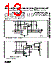
10 / 16 page  START-STOP Software Interrupt The START-STOP interrupt is a method for the slave device to initiate a signal over the 2-wire interface with- out the need for a third (interrupt) wire. A START-STOP interrupt is a start condition followed by a stop condi- tion; in other words, SMBDATA goes low and then high with SMBCLK high (Figure 5 shows the START-STOP interrupt and a subsequent Alert Response transmis- sion used to clear the interrupt). The START-STOP function can be disabled (masked) by setting the data register mask SS (bit 6) high. In order to avoid bus collisions, the START-STOP inter- rupt will not occur when the bus is busy. If the device begins a start condition simultaneously with another transmitter on the bus, it recognizes the falling SMB- CLK as a collision and re-transmits the interrupt when the bus becomes available. Upon thermal shutdown or a transition on an I/O line, the device issues only one START-STOP interrupt, and won’t repeat it unless there has been a collision. However, thermal-shutdown faults, not being edge triggered, may result in a continuous stream of START-STOP bits. Input/Output Pins Each input/output (I/O) is protected by an internal 20mA (typical) current-limit circuit. The I/O current limit depends on the supply voltage and the voltage applied to the I/O pins (see Typical Operating Characteristics). The typical I/O bias current is 0.5µA to VI/O_ = 28V. The ability of the I/Os to sink current depends on VCC as well as the voltage on the I/O. Typical pull-down on- resistance at VCC = 2.7V and 5.5V is 106Ω and 66Ω, respectively. I/O source and sink capability can affect the rise and fall times of external power MOSFETs com- monly used in power-switching applications. Other fac- tors include the VGS, the input capacitance of the MOS- FET, and the pull-up resistor value used in the circuit. Typical MOSFET gate capacitance ranges from 150pF to 2000pF. Increasing the RC time constant slows down the MOSFET’s response, but provides for a smoother transition. Power-On Reset The power-on reset circuit keeps the external MOSFETs off during a power-up sequence. When the supply volt- age falls below the power-on reset threshold voltage, the MAX1662/MAX1663’s outputs reset to a high- impedance state, and the MAX1661’s outputs reset to a low state. During the initial power-up sequence, as VCC increases, the ALERT pin goes low and then high, which indicates the device is powered on. The time between the low and high state on ALERT is the power- on delay time. Below VCC = 0.8V (typical) the POR states can’t be enforced, and the I/O pins of all ver- sions exhibit increasingly weak pull-down current capa- bility, eventually becoming high impedance. Thermal Shutdown These devices have internal thermal-shutdown circuitry that turns off all output stages (I/O pins) when the junc- tion temperature exceeds +140°C typical. Thermal shutdown only occurs during an overload condition on the I/O pins. The device cycles between thermal shut- down and the overcurrent condition until the overload condition is removed. This could cause a sustained START-STOP interrupt and, in the extreme case, tie up the master controller. However, the device asserts ALERT low, indicating this fault status. Serial-to-Parallel/Parallel-to-Serial Converters and Load-Switch Controllers with SMBus Interface 10 ______________________________________________________________________________________ START STOP DATA LINE HELD LOW BY SLAVE SMBCLK SMBDATA tLOW:SS tBUF START-STOP INTERRUPT ALERT RESPONSE ADDRESS (0001100) ACTUAL SLAVE ADDRESS (0100000 IN THIS EXAMPLE) DUMMY BIT (1) ALERT SLAVE ACKNOWLEDGE (ACK) Figure 5. START-STOP Software Interrupt Timing Diagram and Alert Response |
|
|
链接网址 |
| ALLDATASHEET是否为您带来帮助? [ DONATE ] |
关于 Alldatasheet | 广告服务 | 联系我们 | 隐私政策 | 数据表链接 | 链接交换 | 制造商名单 All Rights Reserved©Alldatasheet.com |
| Russian : Alldatasheetru.com | Korean : Alldatasheet.co.kr | Spanish : Alldatasheet.es | French : Alldatasheet.fr | Italian : Alldatasheetit.com Portuguese : Alldatasheetpt.com | Polish : Alldatasheet.pl | Vietnamese : Alldatasheet.vn Indian : Alldatasheet.in | Mexican : Alldatasheet.com.mx | British : Alldatasheet.co.uk | New Zealand : Alldatasheet.co.nz |
|
Family Site : ic2ic.com |
icmetro.com |
 Chinese ▼
 English
 Chinese
 German
 Japanese
 Russian
 Korean
 Spanish
 French
 Italian
 Portuguese
 Polish
 Vietnamese
 Indian
 Mexican
 British
 New Zealand