|
数据搜索系统,热门电子元器件搜索 |
|
|
数据搜索系统,热门电子元器件搜索 |
|
PWR03DPC1O2201 数据表(PDF) 11 Page - Token Electronics Industry Co., Ltd. |
|
|
|||||||||||||||||||||||||||||
PWR03DPC1O2201 数据表(HTML) 11 Page - Token Electronics Industry Co., Ltd. |
|
|
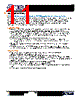
11 / 14 page  http://www.token.com.tw rfq@token.com.tw Taiwan Factory: +886 2 29810109 China Factory: +86 755 26055363 Page: 10/13 Application Notes Pulse Withstanding Chip Resistors (PWR) Application & Soldering Notes Today's electronic devices are becoming smaller and smaller. The requirement, in particular, for pulse withstand capability is growing due to the need to protect sensitive modern electronic systems. To meet this demand Token Electronics have designed a Pulse Withstanding Chip Resistor (PWR Series). The enhanced performance of the chips is made possible by the precise use of the best resistance inks and a closely controlled production process. Application Notes: Applications vary from line protection for telecommunications to surge withstanding resistors for use in circuit breakers. Details of a typical telecomm and power supply application are given below. Telephone lines can be subjected to a large range of voltage disturbances, many of which can damage switching equipment. This has led to the need for circuit protection against both high voltage transients, usually of short duration caused by lighting strikes and overloads of longer duration, due to direct connection to mains power lines. These two faults are separated into primary and secondary protection. 1. Primary protection handles the high voltage transients, and is usually located within the exchange. 2. Secondary protection is usually built into the equipment to be protected, and deals with both current and voltage limiting. Voltage limiting prevents damage to the equipment and shock hazards, and current limiting prevents damage to wiring. To determine the suitability of a (PWR) series chip resistors for your application refer to the pulse withstanding data as given lighting surge performance using both 1.2/50μs and 10/700μs pulse shapes. Soldering Notes: Electrical connection to a ceramic substrate or to a printed circuit board can be made by reflow or wave soldering of wrap-around terminations. Wrap-around terminations provide good leach properties and ensure reliable contact. Due to the robust construction, the (PWR) can be immersed in the solder bath for 30 seconds at 260℃. This enables the resistor to be mounted on one side of a printed circuit board and wire-leaded components applied on the other side. (PWR) resistors themselves can operate at a maximum temperature of 155℃. For soldered resistors, the joint temperature should not exceed 110℃. This condition is met when the stated power levels at 70℃ and recommended pad and trace areas are used. Allowance should be made if smaller areas of copper are used. |
|
|
链接网址 |
| ALLDATASHEET是否为您带来帮助? [ DONATE ] |
关于 Alldatasheet | 广告服务 | 联系我们 | 隐私政策 | 数据表链接 | 链接交换 | 制造商名单 All Rights Reserved©Alldatasheet.com |
| Russian : Alldatasheetru.com | Korean : Alldatasheet.co.kr | Spanish : Alldatasheet.es | French : Alldatasheet.fr | Italian : Alldatasheetit.com Portuguese : Alldatasheetpt.com | Polish : Alldatasheet.pl | Vietnamese : Alldatasheet.vn Indian : Alldatasheet.in | Mexican : Alldatasheet.com.mx | British : Alldatasheet.co.uk | New Zealand : Alldatasheet.co.nz |
|
Family Site : ic2ic.com |
icmetro.com |
 Chinese ▼
 English
 Chinese
 German
 Japanese
 Russian
 Korean
 Spanish
 French
 Italian
 Portuguese
 Polish
 Vietnamese
 Indian
 Mexican
 British
 New Zealand