|
数据搜索系统,热门电子元器件搜索 |
|
|
数据搜索系统,热门电子元器件搜索 |
|
IS25LP032D-RLLA3 数据表(PDF) 68 Page - Integrated Silicon Solution, Inc |
|
|
|||||||||||||||||||||||||||||
IS25LP032D-RLLA3 数据表(HTML) 68 Page - Integrated Silicon Solution, Inc |
|
|
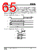
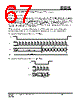
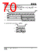
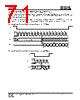
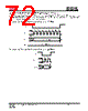
68 / 118 page  IS25LP032D IS25WP032D Integrated Silicon Solution, Inc.- www.issi.com 68 Rev. A12 08/04/2020 Read with “8/16/32/64-Byte Wrap Around” The device is capable of burst read with wrap around in both SPI and QPI mode. The size of burst length is configurable by using P0, P1, and P2 bits in Read Register. P2 bit (Wrap enable) enables the burst mode feature. P0 and P1 define the size of burst. Burst lengths of 8, 16, 32, and 64 bytes are supported. By default, address increases by one up through the entire array. By setting the burst length, the data being accessed can be limited to the length of burst boundary within a 256 byte page. The first output will be the data at the initial address which is specified in the instruction. Following data will come out from the next address within the burst boundary. Once the address reaches the end of boundary, it will automatically move to the first address of the boundary. CE# high will terminate the command. For example, if burst length of 8 and initial address being applied is 0h, following byte output will be from address 00h and continue to 01h,..,07h, 00h, 01h… until CE# terminates the operation. If burst length of 8 and initial address being applied is FEh(254d), following byte output will be from address FEh and continue to FFh, F8h, F9h, FAh, FBh, FCh, FDh, and repeat from FEh until CE# terminates the operation. The commands , “SRPV (65h) or SRPNV (C0h or 63h)”, are used to configure the burst length. If the following data input is one of “00h”,”01h”,”02h”, and ”03h”, the device will be in default operation mode. It will be continuous burst read of the whole array. If the following data input is one of “04h”,”05h”,”06h”, and ”07h”, the device will set the burst length as 8,16,32 and 64, respectively. To exit the burst mode , another “C0h or 63h” command is necessary to set P2 to 0. Otherwise, the burst mode will be retained until either power down or reset operation. To change burst length , another “C0h or 63h” command should be executed to set P0 and P1 (Detailed information in Table 6.9 Burst Length Data). All read commands will operate in burst mode once the Read Register is set to enable burst mode. Refer to Figure 8.40 and Figure 8.41 for instruction sequence. |
|
链接网址 |
| ALLDATASHEET是否为您带来帮助? [ DONATE ] |
关于 Alldatasheet | 广告服务 | 联系我们 | 隐私政策 | 数据表链接 | 链接交换 | 制造商名单 All Rights Reserved©Alldatasheet.com |
| Russian : Alldatasheetru.com | Korean : Alldatasheet.co.kr | Spanish : Alldatasheet.es | French : Alldatasheet.fr | Italian : Alldatasheetit.com Portuguese : Alldatasheetpt.com | Polish : Alldatasheet.pl | Vietnamese : Alldatasheet.vn Indian : Alldatasheet.in | Mexican : Alldatasheet.com.mx | British : Alldatasheet.co.uk | New Zealand : Alldatasheet.co.nz |
|
Family Site : ic2ic.com |
icmetro.com |
 Chinese ▼
 English
 Chinese
 German
 Japanese
 Russian
 Korean
 Spanish
 French
 Italian
 Portuguese
 Polish
 Vietnamese
 Indian
 Mexican
 British
 New Zealand