|
数据搜索系统,热门电子元器件搜索 |
|
|
数据搜索系统,热门电子元器件搜索 |
|
AD8045ACP-R2 数据表(PDF) 20 Page - Analog Devices |
|
|
|||||||||||||||||||||||||||||
AD8045ACP-R2 数据表(HTML) 20 Page - Analog Devices |
|
|
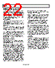
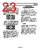
20 / 24 page  AD8045 Rev. A | Page 20 of 24 FREQUENCY (MHz) 0 5 10 15 20 25 30 0 –20 –40 –60 –80 –100 –120 AIN = –1dBFS SNR = 69.9dBc SFDR = 65.3dBc Figure 69. Single-Tone FFT, FIN = 50 MHz, Sample Rate = 65 MSPS Shown in the First Nyquist Zone 90 MHZ ACTIVE LOW-PASS FILTER (LPF) Active filters are used in many applications such as antialiasing filters and high frequency communication IF strips. With a 400 MHz gain bandwidth product and high slew rate, the AD8045 is an ideal candidate for active filters. Figure 70 shows the frequency response of the 90 MHz LPF. In addition to the bandwidth requirements, the slew rate must be capable of supporting the full power bandwidth of the filter. In this case, a 90 MHz bandwidth with a 2 V p-p output swing requires at least 1200 V/µs. This performance is achievable only at 90 MHz because of the AD8045’s wide bandwidth and high slew rate. The circuit shown in Figure 73 is a 90 MHz, 4-pole, Sallen-Key, LPF. The filter comprises two identical cascaded Sallen-Key LPF sections, each with a fixed gain of G = +2. The net gain of the filter is equal to G = +4 or 12 dB. The actual gain shown in Figure 70 is only 6 dB. This is due to the output voltage being divided in half by the series matching termination resistor, RT, and the load resistor. Setting the resistors and capacitors equal to each other greatly simplifies the design equations for the Sallen-Key filter. The corner frequency, or −3 dB frequency, can be described by the equation RC fc 2π 1 = The quality factor, or Q, is shown in the equation K Q − = 3 1 The gain, or K, of the circuits are 1 1, + = + = R7 R8 K Stage Second R4 R3 K Stage First Resistor values are kept low for minimal noise contribution, offset voltage, and optimal frequency response. Due to the low capacitance values used in the filter circuit, the PCB layout and minimization of parasitics is critical. A few picofarads can detune the filters corner frequency, fc. The capacitor values shown in Figure 73 actually incorporate some stray PCB capacitance. Capacitor selection is critical for optimal filter performance. Capacitors with low temperature coefficients, such as NPO ceramic capacitors and silver mica, are good choices for filter elements. FREQUENCY (MHz) 0.1 1 10 100 1000 –40 –30 –20 0 –10 10 –50 –60 –70 –80 –90 20 Figure 70. 90 MHz Low-Pass Filter Response |
|
|
链接网址 |
| ALLDATASHEET是否为您带来帮助? [ DONATE ] |
关于 Alldatasheet | 广告服务 | 联系我们 | 隐私政策 | 数据表链接 | 链接交换 | 制造商名单 All Rights Reserved©Alldatasheet.com |
| Russian : Alldatasheetru.com | Korean : Alldatasheet.co.kr | Spanish : Alldatasheet.es | French : Alldatasheet.fr | Italian : Alldatasheetit.com Portuguese : Alldatasheetpt.com | Polish : Alldatasheet.pl | Vietnamese : Alldatasheet.vn Indian : Alldatasheet.in | Mexican : Alldatasheet.com.mx | British : Alldatasheet.co.uk | New Zealand : Alldatasheet.co.nz |
|
Family Site : ic2ic.com |
icmetro.com |
 Chinese ▼
 English
 Chinese
 German
 Japanese
 Russian
 Korean
 Spanish
 French
 Italian
 Portuguese
 Polish
 Vietnamese
 Indian
 Mexican
 British
 New Zealand