|
数据搜索系统,热门电子元器件搜索 |
|
|
数据搜索系统,热门电子元器件搜索 |
|
AD8137YCP-R2 数据表(PDF) 17 Page - Analog Devices |
|
|
|||||||||||||||||||||||||||||
AD8137YCP-R2 数据表(HTML) 17 Page - Analog Devices |
|
|
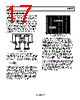
17 / 24 page  AD8137 Rev. B | Page 17 of 24 THEORY OF OPERATION The AD8137 is a low power, low cost, fully differential voltage feedback amplifier that features a rail-to-rail output stage, common-mode circuitry with an internally derived common- mode reference voltage, and bias shutdown circuitry. The amplifier uses two feedback loops to separately control differ- ential and common-mode feedback. The differential gain is set with external resistors as in a traditional amplifier while the output common-mode voltage is set by an internal feedback loop, controlled by an external VOCM input. This architecture makes it easy to arbitrarily set the output common-mode voltage level without affecting the differential gain of the amplifier. –OUT +IN ACM VOCM CC CC CP +OUT –IN CN Figure 61. Block Diagram From Figure 61, the input transconductance stage is an H-bridge whose output current is mirrored to high impedance nodes CP and CN. The output section is traditional H-bridge driven circuitry with common emitter devices driving nodes +OUT and −OUT. The 3 dB point of the amplifier is defined as C m C g BW × π = 2 where gm is the transconductance of the input stage and CC is the total capacitance on node CP/CN (capacitances CP and CN are well matched). For the AD8137, the input stage gm is ~1 mA/V and the capacitance CC is 3.5 pF, setting the crossover frequency of the amplifier at 41 MHz. This frequency generally establishes an amplifier’s unity gain bandwidth, but with the AD8137, the closed-loop bandwidth depends upon the feed- back resistor value as well (see Figure 19). The open-loop gain and phase simulations are shown in Figure 62. FREQUENCY (MHz) 100 80 –60 –40 –20 0 20 40 60 –120 –100 –80 –200 –180 –160 –140 0.0001 0.01 0.001 0.1 1 10 100 OPEN-LOOP GAIN (dB) PHASE (DEGREES) Figure 62. Open-Loop Gain and Phase In Figure 61, the common-mode feedback amplifier ACM samples the output common-mode voltage, and by negative feedback forces the output common-mode voltage to be equal to the voltage applied to the VOCM input. In other words, the feedback loop servos the output common-mode voltage to the voltage applied to the VOCM input. An internal bias generator sets the VOCM level to approximately midsupply; therefore, the output common-mode voltage will be set to approximately midsupply when the VOCM input is left floating. The source resistance of the internal bias generator is large and can be overridden easily by an external voltage supplied by a source with a relatively small output resistance. The VOCM input can be driven to within approximately 1 V of the supply rails while maintaining linear operation in the common-mode feedback loop. The common-mode feedback loop inside the AD8137 produces outputs that are highly balanced over a wide frequency range without the requirement of tightly matched external compo- nents, because it forces the signal component of the output common-mode voltage to be zeroed. The result is nearly perfectly balanced differential outputs of identical amplitude and exactly 180° apart in phase. |
|
|
链接网址 |
| ALLDATASHEET是否为您带来帮助? [ DONATE ] |
关于 Alldatasheet | 广告服务 | 联系我们 | 隐私政策 | 数据表链接 | 链接交换 | 制造商名单 All Rights Reserved©Alldatasheet.com |
| Russian : Alldatasheetru.com | Korean : Alldatasheet.co.kr | Spanish : Alldatasheet.es | French : Alldatasheet.fr | Italian : Alldatasheetit.com Portuguese : Alldatasheetpt.com | Polish : Alldatasheet.pl | Vietnamese : Alldatasheet.vn Indian : Alldatasheet.in | Mexican : Alldatasheet.com.mx | British : Alldatasheet.co.uk | New Zealand : Alldatasheet.co.nz |
|
Family Site : ic2ic.com |
icmetro.com |
 Chinese ▼
 English
 Chinese
 German
 Japanese
 Russian
 Korean
 Spanish
 French
 Italian
 Portuguese
 Polish
 Vietnamese
 Indian
 Mexican
 British
 New Zealand