|
数据搜索系统,热门电子元器件搜索 |
|
|
数据搜索系统,热门电子元器件搜索 |
|
AD8137YCP-R2 数据表(PDF) 18 Page - Analog Devices |
|
|
|||||||||||||||||||||||||||||
AD8137YCP-R2 数据表(HTML) 18 Page - Analog Devices |
|
|
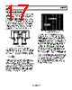
18 / 24 page  AD8137 Rev. B | Page 18 of 24 APPLICATIONS ANALYZING A TYPICAL APPLICATION WITH MATCHED RF AND RG NETWORKS Typical Connection and Definition of Terms Figure 63 shows a typical connection for the AD8137, using matched external RF/RG networks. The differential input terminals of the AD8137, VAP and VAN, are used as summing junctions. An external reference voltage applied to the VOCM terminal sets the output common-mode voltage. The two output terminals, VOP and VON, move in opposite directions in a balanced fashion in response to an input signal. + – VAP VAN VON VOP – + VO, dm RL, dm AD8137 CF RF RG RG CF RF VIP VOCM VIN Figure 63. Typical Connection The differential output voltage is defined as ON OP dm O, V V V − = (1) Common-mode voltage is the average of two voltages. The output common-mode voltage is defined as 2 , ON OP cm O V V V + = (2) Output Balance Output balance is a measure of how well VOP and VON are matched in amplitude and how precisely they are 180° out of phase with each other. It is the internal common-mode feed- back loop that forces the signal component of the output common-mode towards zero, resulting in the near perfectly balanced differential outputs of identical amplitude and exactly 180° out of phase. The output balance performance does not require tightly matched external components, nor does it require that the feedback factors of each loop be equal to each other. Low frequency output balance is ultimately limited by the mismatch of an on-chip voltage divider. Output balance is measured by placing a well-matched resistor divider across the differential voltage outputs and comparing the signal at the divider’s midpoint with the magnitude of the differential output. By this definition, output balance is equal to the magnitude of the change in output common-mode voltage divided by the magnitude of the change in output differential- mode voltage: dm O cm O V V Balance Output , , ∆ ∆ = (3) The differential negative feedback drives the voltages at the summing junctions VAN and VAP to be essentially equal to each other. AP AN V V = (4) The common-mode feedback loop drives the output common- mode voltage, sampled at the midpoint of the two internal common-mode tap resistors in Figure 61, to equal the voltage set at the VOCM terminal. This ensures that 2 , dm O OCM OP V V V + = (5) and 2 , dm O OCM ON V V V − = (6) ESTIMATING NOISE, GAIN, AND BANDWITH WITH MATCHED FEEDBACK NETWORKS Estimating Output Noise Voltage and Bandwidth The total output noise is the root-sum-squared total of several statistically independent sources. Since the sources are statisti- cally independent, the contributions of each must be individu- ally included in the root-sum-square calculation. Table 7 lists recommended resistor values and estimates of bandwidth and output differential voltage noise for various closed-loop gains. For most applications, 1% resistors are sufficient. Table 7. Recommended Values of Gain-Setting Resistors, and Voltage Gain for Various Closed-Loop Gains Gain RG (Ω) RF (Ω) 3 dB Bandwidth (MHz) Total Output Noise (nV/√Hz) 1 1 k 1 k 72 18.6 2 1 k 2 k 40 28.9 5 1 k 5 k 12 60.1 10 1 k 10 k 6 112.0 |
|
|
链接网址 |
| ALLDATASHEET是否为您带来帮助? [ DONATE ] |
关于 Alldatasheet | 广告服务 | 联系我们 | 隐私政策 | 数据表链接 | 链接交换 | 制造商名单 All Rights Reserved©Alldatasheet.com |
| Russian : Alldatasheetru.com | Korean : Alldatasheet.co.kr | Spanish : Alldatasheet.es | French : Alldatasheet.fr | Italian : Alldatasheetit.com Portuguese : Alldatasheetpt.com | Polish : Alldatasheet.pl | Vietnamese : Alldatasheet.vn Indian : Alldatasheet.in | Mexican : Alldatasheet.com.mx | British : Alldatasheet.co.uk | New Zealand : Alldatasheet.co.nz |
|
Family Site : ic2ic.com |
icmetro.com |
 Chinese ▼
 English
 Chinese
 German
 Japanese
 Russian
 Korean
 Spanish
 French
 Italian
 Portuguese
 Polish
 Vietnamese
 Indian
 Mexican
 British
 New Zealand