|
数据搜索系统,热门电子元器件搜索 |
|
|
数据搜索系统,热门电子元器件搜索 |
|
ADL5904ACPZN-R7 数据表(PDF) 26 Page - Analog Devices |
|
|
|||||||||||||||||||||||||||||
ADL5904ACPZN-R7 数据表(HTML) 26 Page - Analog Devices |
|
|
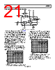
26 / 27 page  ADL5904 Data Sheet Rev. B | Page 26 of 27 Table 7. Evaluation Board Configuration Options Component Function Notes Default Values RFIN, R1, R2, R3, R8, R9, R10, L1, L2, C2, C4, C5 RF input Apply the RF input signal to the ADL5904 to the SMA connector labeled RFIN. The ADL5904 RFIN pin (Pin 1) is dc-coupled and is not internally matched. A broadband 50 Ω match is achieved using an external 82.5 Ω shunt resistor with a 0.47 µF ac coupling capacitor placed between the shunt resistor and the RF input. An external preemphasis network can be built to improve flatness vs. frequency using the components between R8 and the RFIN SMA connector. C4= 0.47uF (0402) R8 = 82.5 Ω (0402) R2, R9, R10 = 0 Ω (0402) R1, R3 = open (0402) L1, L2 = open (0402) C2, C5 = open (0402) VCAL, VIN_N, TPVIN_N, C17, VCAL threshold calibration The output voltage from the threshold calibration pin (VCAL, Pin 3) is available on the yellow VCAL clip lead. Use the voltage on this pin to determine the correct threshold voltage that must be applied to Pin 16 (VIN−) to set a particular RF power threshold. This process includes two steps: first, measure the output voltage on the VCAL yellow clip lead with no RF signal applied to RFIN (this voltage is approximately 750 mV). Next, apply the RF input power to RFIN, which causes the circuit to trip, and again measure the voltage on the VCAL yellow clip lead. The difference between these two voltages is equal to the voltage that must be applied to VIN− during operation. This voltage can be applied either to the VIN_N SMA connector or to the TPVIN_N yellow clip lead. Use C17 to provide noise decoupling of the applied input voltage. C17 = open (0603) R6, C3 DECL internal decoupling node A resistor in series with a capacitor to ground must be connected to the DECL pin (Pin 4). C3 = 100 nF (0402) R6 = 4.02 Ω (0402) VPOS, GND, C7, C6 Power supply interface Apply the 3.3 V power supply for the evaluation board to the VPOS (red) and GND (black) test loops. The nominal supply decoupling consists of a 100 pF capacitor and a 0.1 µF capacitor, with the 100 pF capacitor placed closest to the VPOS pin (Pin 5). C7 = 0.1 µF (0402), C6 = 100 pF (0402) VPOS = 3.3 V VRMS, TP1, R16, C14 Output interface The rms output voltage is available on the VRMS SMA connector or on the TP1 yellow clip lead. R16 = 0 Ω (0402) C14 = 10 nF (0603) C12 RMS averaging capacitor Set the value of the rms averaging capacitor based on the peak to average ratio and bandwidth of the input signal and based on the desired output response time and residual output noise. C12 = 0.1 µF (0402) Q, Q, QX, QX, R19, R21, C15, C16 Threshold detect output (Q and Q) The threshold detect flip flop outputs (Q and Q) are available on the SMA connectors labeled Q and Q and on the 2-pin headers labeled QX and QX. To test the response time of Q and Q, remove R19 and R21 and probe QX and QX with low capacitance FET probes. C15 = C16 = open (0603) R19, R21 = 0 Ω (0603) ENBL, S1, R31 Enable interface The ADL5904 can be enabled by applying 3.3 V to the ENBL SMA connector or using the S1 switch. The enable voltage must be equal to but not greater than the 3.3 V supply voltage. R31 = 10 kΩ (0603) RST push-button switch, R4, C1, R28 Threshold detect reset The threshold detect flip-flop is reset using the RST push-button switch. The RST switch is connected the VPOS supply voltage through a 1.1 kΩ resistor (R28). A 100 kΩ pull-down resistor (R4) is connected to the RST pin, which pulls RST low in the absence of any other stimulus. The ADL5904 normally powers up with the Q and Q outputs high and low, respectively. A reset on the power-up circuit can be implemented by installing a capacitor on C1. When the VPOS supply turns on, RST goes high momentarily before being pulled low by R4. R4 = 10 kΩ (0603) R28 = 1.1 kΩ (0603) C1 = open (0603) VIN_N, TPVIN_N, C17 Threshold detect level set The voltage applied to the VIN_N SMA connector or to the TPVIN_N yellow test loop drives the inverting input of the threshold detect comparator (VIN−) and thereby defines the RF power level that trips the threshold detect comparator and flip flop. The threshold detect voltage can be optionally decoupled using C17. C17 = open (0603) |
|
|
链接网址 |
| ALLDATASHEET是否为您带来帮助? [ DONATE ] |
关于 Alldatasheet | 广告服务 | 联系我们 | 隐私政策 | 数据表链接 | 链接交换 | 制造商名单 All Rights Reserved©Alldatasheet.com |
| Russian : Alldatasheetru.com | Korean : Alldatasheet.co.kr | Spanish : Alldatasheet.es | French : Alldatasheet.fr | Italian : Alldatasheetit.com Portuguese : Alldatasheetpt.com | Polish : Alldatasheet.pl | Vietnamese : Alldatasheet.vn Indian : Alldatasheet.in | Mexican : Alldatasheet.com.mx | British : Alldatasheet.co.uk | New Zealand : Alldatasheet.co.nz |
|
Family Site : ic2ic.com |
icmetro.com |
 Chinese ▼
 English
 Chinese
 German
 Japanese
 Russian
 Korean
 Spanish
 French
 Italian
 Portuguese
 Polish
 Vietnamese
 Indian
 Mexican
 British
 New Zealand