|
数据搜索系统,热门电子元器件搜索 |
|
|
数据搜索系统,热门电子元器件搜索 |
|
STDRIVE101TR 数据表(PDF) 17 Page - STMicroelectronics |
|
|
|||||||||||||||||||||||||||||
STDRIVE101TR 数据表(HTML) 17 Page - STMicroelectronics |
|
|
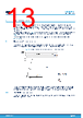
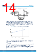
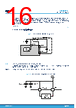
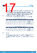
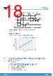
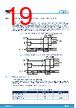
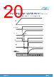
17 / 32 page  5.3 Control logic The device integrates a control logic providing two input strategies. The driving method is selected according to DT/MODE pin status: • DT/MODE connected to the ground through an RDT resistor: digital inputs provide enable and input lines for each half-bridge and an internal deadtime is generated according to RDT value (ENx/INx mode). • DT/MODE shorted to ground: digital inputs provide high and low-side driving lines for each half-bridge, no deadtime is internally generated (INHx/INLx mode). In any case, the high and low-side outputs of same half- bridge cannot be simultaneously driven high because of the integrated interlocking function. Note: The DT/MODE pin status must not be changed during device operation. All the input lines have an internal pull-down to guarantee the low logic level even if no driving input is present. Table 7. INxL and INxH inputs truth table INxH INxL GHSx GHLx ‘x’ Half-bridge condition L L L L Disabled L H L H Low-side on H L H L High-side on H H L L Disabled (interlocking) Table 8. ENx and INx inputs truth table ENx INx GHSx GLSx ‘x’ Half-bridge condition L X L L Disabled H L L H Low-side on H H H L High-side on Note: X: don't care 5.3.1 Deadtime When the DT/MODE pin is connected to the ground through an RDT resistor (ENx/INx mode selected), the device internally generates a deadtime between the MOSFET turn-off and the turn-on of the opposite one. Input pulses shorter than the deadtime cause an immediate turn on of the gate driver, back to the former status as shown in Figure 13. STDRIVE101 Control logic DS13472 - Rev 1 page 17/32 |
|
链接网址 |
| ALLDATASHEET是否为您带来帮助? [ DONATE ] |
关于 Alldatasheet | 广告服务 | 联系我们 | 隐私政策 | 数据表链接 | 链接交换 | 制造商名单 All Rights Reserved©Alldatasheet.com |
| Russian : Alldatasheetru.com | Korean : Alldatasheet.co.kr | Spanish : Alldatasheet.es | French : Alldatasheet.fr | Italian : Alldatasheetit.com Portuguese : Alldatasheetpt.com | Polish : Alldatasheet.pl | Vietnamese : Alldatasheet.vn Indian : Alldatasheet.in | Mexican : Alldatasheet.com.mx | British : Alldatasheet.co.uk | New Zealand : Alldatasheet.co.nz |
|
Family Site : ic2ic.com |
icmetro.com |
 Chinese ▼
 English
 Chinese
 German
 Japanese
 Russian
 Korean
 Spanish
 French
 Italian
 Portuguese
 Polish
 Vietnamese
 Indian
 Mexican
 British
 New Zealand