|
数据搜索系统,热门电子元器件搜索 |
|
|
数据搜索系统,热门电子元器件搜索 |
|
ADP1613ARMZ-R7 数据表(PDF) 13 Page - Analog Devices |
|
|
|||||||||||||||||||||||||||||
ADP1613ARMZ-R7 数据表(HTML) 13 Page - Analog Devices |
|
|
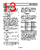
13 / 28 page  ADP1612/ADP1613 Rev. A | Page 13 of 28 APPLICATIONS INFORMATION SETTING THE OUTPUT VOLTAGE The ADP1612/ADP1613 feature an adjustable output voltage range of VIN to 20 V. The output voltage is set by the resistor voltage divider, R1 and R2, (see Figure 34) from the output voltage (VOUT) to the 1.235 V feedback input at FB. Use the following equation to determine the output voltage: VOUT = 1.235 × (1 + R1/R2) (1) Choose R1 based on the following equation: ⎟ ⎠ ⎞ ⎜ ⎝ ⎛ − × = 235 . 1 235 . 1 OUT V R2 R1 (2) INDUCTOR SELECTION The inductor is an essential part of the step-up switching converter. It stores energy during the on time of the power switch, and transfers that energy to the output through the output rectifier during the off time. To balance the tradeoffs between small inductor current ripple and efficiency, induc- tance values in the range of 4.7 μH to 22 μH are recommended. In general, lower inductance values have higher saturation current and lower series resistance for a given physical size. However, lower inductance results in a higher peak current that can lead to reduced efficiency and greater input and/or output ripple and noise. A peak-to-peak inductor ripple current close to 30% of the maximum dc input current typically yields an optimal compromise. For determining the inductor ripple current in continuous operation, the input (VIN) and output (VOUT) voltages determine the switch duty cycle (D) by the following equation: OUT IN OUT V V V D − = (3) Using the duty cycle and switching frequency, fSW, determine the on time by the following equation: SW ON f D t = (4) The inductor ripple current (ΔIL) in steady state is calculated by L t V I ON IN L × = Δ (5) Solve for the inductance value (L) by the following equation: L ON IN I t V L Δ × = (6) Ensure that the peak inductor current (the maximum input current plus half the inductor ripple current) is below the rated saturation current of the inductor. Likewise, make sure that the maximum rated rms current of the inductor is greater than the maximum dc input current to the regulator. For CCM duty cycles greater than 50% that occur with input voltages less than one-half the output voltage, slope compen- sation is required to maintain stability of the current-mode regulator. For stable current-mode operation, ensure that the selected inductance is equal to or greater than the minimum calculated inductance, LMIN, for the application parameters in the following equation: SW IN OUT MIN f V V L L × × − = > 7 . 2 ) 2 ( (7) Inductors smaller than the 4.7 μH to 22 μH recommended range can be used as long as Equation 7 is satisfied for the given application. For input/output combinations that approach the 90% maximum duty cycle, doubling the inductor is recom- mended to ensure stable operation. Table 5 suggests a series of inductors for use with the ADP1612/ADP1613. Table 5. Suggested Inductors Manufacturer Part Series Dimensions L × W × H (mm) Sumida CMD4D11 5.8 × 4.4 × 1.2 CDRH4D28CNP 5.1 × 5.1 × 3.0 CDRH5D18NP 6.0 × 6.0 × 2.0 CDRH6D26HPNP 7.0 × 7.0 × 2.8 Coilcraft DO3308P 12.95 × 9.4 × 3.0 DO3316P 12.95 × 9.4 × 5.21 Toko D52LC 5.2 × 5.2 × 2.0 D62LCB 6.2 × 6.3 × 2.0 D63LCB 6.2 × 6.3 × 3.5 Würth Elektronik WE-TPC Assorted WE-PD, PD2, PD3, PD4 Assorted CHOOSING THE INPUT AND OUTPUT CAPACITORS The ADP1612/ADP1613 require input and output bypass capa- citors to supply transient currents while maintaining constant input and output voltages. Use a low equivalent series resistance (ESR), 10 μF or greater input capacitor to prevent noise at the ADP1612/ADP1613 input. Place the capacitor between VIN and GND as close to the ADP1612/ADP1613 as possible. Ceramic capacitors are preferred because of their low ESR characteristics. Alternatively, use a high value, medium ESR capacitor in parallel with a 0.1 μF low ESR capacitor as close to the ADP1612/ADP1613 as possible. |
|
|
链接网址 |
| ALLDATASHEET是否为您带来帮助? [ DONATE ] |
关于 Alldatasheet | 广告服务 | 联系我们 | 隐私政策 | 数据表链接 | 链接交换 | 制造商名单 All Rights Reserved©Alldatasheet.com |
| Russian : Alldatasheetru.com | Korean : Alldatasheet.co.kr | Spanish : Alldatasheet.es | French : Alldatasheet.fr | Italian : Alldatasheetit.com Portuguese : Alldatasheetpt.com | Polish : Alldatasheet.pl | Vietnamese : Alldatasheet.vn Indian : Alldatasheet.in | Mexican : Alldatasheet.com.mx | British : Alldatasheet.co.uk | New Zealand : Alldatasheet.co.nz |
|
Family Site : ic2ic.com |
icmetro.com |
 Chinese ▼
 English
 Chinese
 German
 Japanese
 Russian
 Korean
 Spanish
 French
 Italian
 Portuguese
 Polish
 Vietnamese
 Indian
 Mexican
 British
 New Zealand