|
数据搜索系统,热门电子元器件搜索 |
|
|
数据搜索系统,热门电子元器件搜索 |
|
ADRF6510ACPZ-R7 数据表(PDF) 20 Page - Analog Devices |
|
|
|||||||||||||||||||||||||||||
ADRF6510ACPZ-R7 数据表(HTML) 20 Page - Analog Devices |
|
|
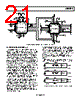
20 / 28 page  ADRF6510 Rev. 0 | Page 20 of 28 An overall RF-to-baseband EVM performance was obtained with the ADL5387 IQ demodulator preceding the ADRF6510. An 840 MHz RF signal with a modulation setting of 64 QAM and a 7 MHz symbol rate was used. The local oscillator (LO) is set at 1680 MHz to obtain 840 MHz at the quadrature core after the divide-by-2 stage. The analog gain of the ADRF6510 was adjusted to maintain 1.5 V p-p into a 1 kΩ load impedance. Figure 49 shows EVM vs. input power and the corresponding analog gain voltage. 32 20 –65 –5 RF INPUT POWER (dBm) 0.5 0 1.0 1.5 2.0 2.5 22 24 26 28 30 –55 –45 –35 –25 –15 Figure 49. EVM vs. RF Input Power Level LOW IF IMAGE REJECTION The image rejection ratio is the ratio of the intermediate frequency (IF) signal level produced by the desired input frequency to that produced by the image frequency. The image rejection ratio is expressed in decibels (dB). Appropriate image rejection is critical because the image power can be much higher than that of the desired signal, thereby plaguing the downconversion process. Figure 51 illustrates the image problem. If the upper sideband is the desired band, a 90° shift to the Q channel cancels the image at the lower sideband. In the same way, if the lower sideband is the desired band, a 90° shift to the I channel cancels the image at the upper sideband. Phase and gain balance between the I and Q channels are critical for high levels of image rejection. Figure 50 shows the image rejection of the ADL5387 and the ADRF6510 for various baseband frequencies. The modulation is 64 QAM with a 7 MHz symbol rate. Note the following: • To the right of the 5 MHz center frequency, the filter is programmed to be 5 MHz greater than the centered base- band frequency. This ensures that the signal edge is well within the pass band of the filter. In such cases, where the filter bandwidth is set to be greater than the signal bandwidth, the image rejection of the ADL5387 tends to be the limiting factor, and the ADRF6510 has minimal effects. • To the left of 5 MHz—specifically at a center frequency of 3.5 MHz—the filter corner is lowered to the baseband signal edge, degrading the image rejection. When the centered baseband frequency is 3.5 MHz and the filter is set at 7 MHz (instead of a safer 8 MHz), the filter corner conflicts with the edge of the modulated signal. Channel mismatch in group delay characteristics and variation in absolute group delay (from the normal flat response) tend to degrade image rejection. 45 0 31 BASEBAND FREQUENCY (MHz) 5 5 10 15 20 25 30 35 40 579 11 13 AT CENTER FREQUENCY = 3.5MHz, FILTER CORNER IS SET TO 7MHz AT CENTER FREQUENCIES GREATER THAN 5MHz, FILTER CORNER IS SET TO 5MHz HIGHER THAN SIGNAL EDGE Figure 50. Image Rejection of the ADL5387 and ADRF6510 0° 0° 0 0 0 0 –90° +90° ωIF ω IF ωLSB ω LO ω USB SIN ωLOt COS ωLOt – ωIF + ωIF – ωIF + ωIF + ωIF + ωIF Figure 51. Illustration of the Image Problem |
|
|
链接网址 |
| ALLDATASHEET是否为您带来帮助? [ DONATE ] |
关于 Alldatasheet | 广告服务 | 联系我们 | 隐私政策 | 数据表链接 | 链接交换 | 制造商名单 All Rights Reserved©Alldatasheet.com |
| Russian : Alldatasheetru.com | Korean : Alldatasheet.co.kr | Spanish : Alldatasheet.es | French : Alldatasheet.fr | Italian : Alldatasheetit.com Portuguese : Alldatasheetpt.com | Polish : Alldatasheet.pl | Vietnamese : Alldatasheet.vn Indian : Alldatasheet.in | Mexican : Alldatasheet.com.mx | British : Alldatasheet.co.uk | New Zealand : Alldatasheet.co.nz |
|
Family Site : ic2ic.com |
icmetro.com |
 Chinese ▼
 English
 Chinese
 German
 Japanese
 Russian
 Korean
 Spanish
 French
 Italian
 Portuguese
 Polish
 Vietnamese
 Indian
 Mexican
 British
 New Zealand