|
数据搜索系统,热门电子元器件搜索 |
|
|
数据搜索系统,热门电子元器件搜索 |
|
ADRF6510ACPZ-R7 数据表(PDF) 21 Page - Analog Devices |
|
|
|||||||||||||||||||||||||||||
ADRF6510ACPZ-R7 数据表(HTML) 21 Page - Analog Devices |
|
|
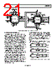
21 / 28 page  ADRF6510 Rev. 0 | Page 21 of 28 VPSD COMD LE CLK DATA SDO COM VPS OPP1 OPM1 COM GAIN VOCM COM OPM2 OPP2 COM INP2 INM2 VPS COM OFDS OFS2 VPS ENBL INP1 INM1 VPS COM GNSW OFS1 VPS ADRF6510 VPS VPS VPSD 0.1µF VPS VPS VPS VPS R2 VPS 0.1µF 0.1µF 0.1µF 0.1µF 0.1µF 0.1µF VPS RFC 1000pF 100pF 0.1µF 1000pF 100pF 0.1µF 100pF 0.1µF VPOS VPOS LO 1000pF 1000pF VPOS ETC1-1-13 1 ADL5387 24 23 22 21 20 19 78 9 10 11 12 2 3 4 5 6 VPA COM BIAS VPL VPL VPL 18 17 16 15 14 13 VPB VPB QHI QLO IHI ILO 120nH 120nH Figure 52. ADL5387 and ADRF6510 Interfacing Example—Block Diagram EXAMPLE BASEBAND INTERFACE The noise spectral density of the ADRF6510 outside the filter bandwidth is limited by the fixed VGA output noise. It may be necessary to use an external, fixed-frequency, passive filter prior to an analog-to-digital conversion to prevent noise aliasing from degrading the signal-to-noise ratio. As shown in Figure 46 and Figure 47, the noise density at higher frequencies tends to be flat, and any higher IF noise aliasing into the Nyquist zone has minimal effects. Using the AD9639, a 12-bit ADC with a 210 MSPS sam- pling rate, the effects of an antialiasing filter present between the ADRF6510 and the ADC showed a minimal 1.5 dB improvement. When designing an antialiasing filter, it is necessary to consider the overall source and load impedance presented by the ADRF6510 and the ADC input to design the filter network. The differential baseband output impedance of the ADRF6510 is 20 Ω and is designed to drive a high impedance ADC input. It may be desirable to terminate the ADC input to a lower impedance by using a terminating resistor, such as 500 Ω. The terminating resistor helps to better define the input impedance at the ADC input at the cost of a slightly reduced gain. The order and type of filter network depend on the desired high frequency rejection required, the pass-band ripple, and the group delay. Filter design tables provide outlines for various filter types and orders, illustrating the normalized inductor and capacitor values for a 1 Hz cutoff frequency and 1 Ω load. After scaling the normalized prototype element values by the actual desired cutoff frequency and load impedance, the series reactance elements are halved to realize the final balanced filter network component values. As an example, a second-order Butterworth, low-pass filter design is shown in Figure 53 where the differential load impedance is 500 Ω and the source impedance is 50 Ω. The normalized series inductor value for the 10-to-1, load-to-source impedance ratio is 0.074 H, and the normalized shunt capacitor is 14.814 F. For a 10.9 MHz cutoff frequency, the single-ended equivalent circuit consists of a 0.54 μH series inductor followed by a 433 pF shunt capacitor. The balanced configuration is realized as the 0.54 μH inductor is split in half to achieve the network that is shown in Figure 53. VS RS 2 RS RL RS 2 RL 2 RL 2 433pF VS RS = 50Ω RL = 500Ω 0.54µH 0.27µH 0.27µH 433pF BALANCED CONFIGURATION DENORMALIZED SINGLE-ENDED EQUIVALENT VS RS = 50Ω = 0.1 Ω RL = 500Ω LN = 0.074H CN 14.814F NORMALIZED SINGLE-ENDED CONFIGURATION = 25 Ω = 25 Ω = 250 Ω = 250 Ω fC = 10.9MHz fC = 1Hz Figure 53. Second-Order Butterworth, Low-Pass Filter Design Example |
|
|
链接网址 |
| ALLDATASHEET是否为您带来帮助? [ DONATE ] |
关于 Alldatasheet | 广告服务 | 联系我们 | 隐私政策 | 数据表链接 | 链接交换 | 制造商名单 All Rights Reserved©Alldatasheet.com |
| Russian : Alldatasheetru.com | Korean : Alldatasheet.co.kr | Spanish : Alldatasheet.es | French : Alldatasheet.fr | Italian : Alldatasheetit.com Portuguese : Alldatasheetpt.com | Polish : Alldatasheet.pl | Vietnamese : Alldatasheet.vn Indian : Alldatasheet.in | Mexican : Alldatasheet.com.mx | British : Alldatasheet.co.uk | New Zealand : Alldatasheet.co.nz |
|
Family Site : ic2ic.com |
icmetro.com |
 Chinese ▼
 English
 Chinese
 German
 Japanese
 Russian
 Korean
 Spanish
 French
 Italian
 Portuguese
 Polish
 Vietnamese
 Indian
 Mexican
 British
 New Zealand