|
数据搜索系统,热门电子元器件搜索 |
|
|
数据搜索系统,热门电子元器件搜索 |
|
AD8142ACPZ-R2 数据表(PDF) 20 Page - Analog Devices |
|
|
|||||||||||||||||||||||||||||
AD8142ACPZ-R2 数据表(HTML) 20 Page - Analog Devices |
|
|
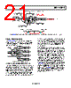
20 / 24 page  AD8141/AD8142 Rev. 0 | Page 20 of 24 AD8142 SIGNAL LEVELS ON VARIOUS SUPPLIES Figure 44 and Figure 45 illustrate the key video signal levels seen in typical applications operating on a single +5 V supply and ±2.5 V supplies; common-mode sync pulses are omitted from the circuit drawing for clarity but are shown in a separate waveform drawing of the signals directly at the AD8142 outputs, shown just below the associated circuit drawing. The sync pulses are common-mode, that is, they move in the same direction on each output polarity. In Figure 44 and Figure 45, this means that the HSYNC pulses are either both green or both blue for the red and black video signals. DISABLE FEATURE When asserted, the disable feature minimizes quiescent current consumption and provides a high-Z output. It offers a convenient means to connect two driver outputs together in parallel to form a tristate multiplexed application. The disable feature can also be used to minimize quiescent current drawn when a particular device is not being used. The disable pin is a binary input that controls the state of the AD8141/AD8142 outputs. Its binary input levels are compatible with most TTL and CMOS families (see Table 1 for the logic levels). The AD8141/AD8142output is disabled when the disable input is driven to its high state, and the AD8141/AD8142operates in its normal fashion when the disable input is driven to its low state. An unavoidable common-mode glitch occurs at the outputs when switching between disabled and enabled states and vice versa. The glitch lasts for a few tens of nanoseconds and is on the order of 2 V or 3 V. If the disable feature is used, it is recommended that common-mode protection be used on the receiver (see the AD8143 data sheet for a detailed description of common-mode protection) AD8142 + – 49.9Ω 1kΩ 38.3Ω 80.6Ω 0.76V 0.52V 1kΩ 2kΩ +5V 2kΩ 100Ω 100Ω UTP 49.9Ω 0.7V 1.5V 2.2V 1.5V 1.5V 0.8V 0.7V 0V 75Ω VIDEO SOURCE 1.4V 1.5V 0.8V 2.2V 0.5V AD8142 KEY SIGNAL LEVELS ON SINGLE +5V SUPPLY AD8142 OUTPUT SIGNAL LEVELS INCLUDING COMMON-MODE HSYNC PULSES Figure 44. AD8142 Key Signal Levels on Single 5 V Supply; Upper Drawing Shows Schematic, and Lower Drawing Shows Output Signals with HSYNC Pulses |
|
|
链接网址 |
| ALLDATASHEET是否为您带来帮助? [ DONATE ] |
关于 Alldatasheet | 广告服务 | 联系我们 | 隐私政策 | 数据表链接 | 链接交换 | 制造商名单 All Rights Reserved©Alldatasheet.com |
| Russian : Alldatasheetru.com | Korean : Alldatasheet.co.kr | Spanish : Alldatasheet.es | French : Alldatasheet.fr | Italian : Alldatasheetit.com Portuguese : Alldatasheetpt.com | Polish : Alldatasheet.pl | Vietnamese : Alldatasheet.vn Indian : Alldatasheet.in | Mexican : Alldatasheet.com.mx | British : Alldatasheet.co.uk | New Zealand : Alldatasheet.co.nz |
|
Family Site : ic2ic.com |
icmetro.com |
 Chinese ▼
 English
 Chinese
 German
 Japanese
 Russian
 Korean
 Spanish
 French
 Italian
 Portuguese
 Polish
 Vietnamese
 Indian
 Mexican
 British
 New Zealand