|
数据搜索系统,热门电子元器件搜索 |
|
|
数据搜索系统,热门电子元器件搜索 |
|
AD8420ARMZ-R7 数据表(PDF) 25 Page - Analog Devices |
|
|
|||||||||||||||||||||||||||||
AD8420ARMZ-R7 数据表(HTML) 25 Page - Analog Devices |
|
|
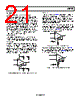
25 / 28 page  Data Sheet AD8420 Rev. 0 | Page 25 of 28 CLASSIC BRIDGE CIRCUIT Figure 70 shows the AD8420 configured to amplify the signal from a classic resistive bridge. This circuit works in dual-supply mode or single-supply mode. Typically, the same voltage that powers the instrumentation amplifier excites the bridge. Connecting the bottom of the bridge to the negative supply of the instrumentation amplifier sets up an input common-mode voltage that is located midway between the supply voltages. The voltage on the REF pin can be varied to suit the application. For example, the REF pin is tied to the VREF pin of an analog-to-digital converter (ADC) whose input range is (VREF ± VIN). With an available output swing on the AD8420 of (−VS + 100 mV) to (+VS − 150 mV), the maximum programmable gain is simply this output range divided by the input range. +VS –VS 0.1µF 0.1µF VOUT VREF VDIFF AD8420 Figure 70. Classic Bridge Circuit 4 mA TO 20 mA SINGLE-SUPPLY RECEIVER The 80 μA maximum supply current, input range that goes below ground, and low drift characteristics make the AD8420 a very good candidate for use in a 4 mA to 20 mA loop. Figure 71 shows how a signal from a 4 mA to 20 mA transducer can be interfaced to the AD8420. The signal from a 4 mA to 20 mA transducer is single-ended, which initially suggests the need for a simple shunt resistor to ground to convert the current to a voltage. However, any line resistance in the return path (to the transducer) adds a current-dependent offset error; therefore, the current must be sensed differentially. In this example, a 5 Ω shunt resistor generates a differential voltage at the inputs of the AD8420 between 20 mV (for 4 mA in) and 100 mV (for 20 mA in) with a very low common-mode value. With the gain resistors shown, the AD8420 amplifies the 100 mV input voltage by a factor of 40 to 4.0 V. AD627 LINE IMPEDANCE 4mA TO 20mA 5Ω 4mA TO 20mA TRANSDUCER R2 = 97.6kΩ R1 = 2.49kΩ 0.1µF 5V AD8420 R2 R1 G = 40 POWER SUPPLY + – + – 0.8V TO 4.0V Figure 71. 4 mA to 20 mA Receiver Circuit |
|
|
链接网址 |
| ALLDATASHEET是否为您带来帮助? [ DONATE ] |
关于 Alldatasheet | 广告服务 | 联系我们 | 隐私政策 | 数据表链接 | 链接交换 | 制造商名单 All Rights Reserved©Alldatasheet.com |
| Russian : Alldatasheetru.com | Korean : Alldatasheet.co.kr | Spanish : Alldatasheet.es | French : Alldatasheet.fr | Italian : Alldatasheetit.com Portuguese : Alldatasheetpt.com | Polish : Alldatasheet.pl | Vietnamese : Alldatasheet.vn Indian : Alldatasheet.in | Mexican : Alldatasheet.com.mx | British : Alldatasheet.co.uk | New Zealand : Alldatasheet.co.nz |
|
Family Site : ic2ic.com |
icmetro.com |
 Chinese ▼
 English
 Chinese
 German
 Japanese
 Russian
 Korean
 Spanish
 French
 Italian
 Portuguese
 Polish
 Vietnamese
 Indian
 Mexican
 British
 New Zealand