|
数据搜索系统,热门电子元器件搜索 |
|
|
数据搜索系统,热门电子元器件搜索 |
|
LED5000 数据表(PDF) 23 Page - STMicroelectronics |
|
|
|||||||||||||||||||||||||||||
LED5000 数据表(HTML) 23 Page - STMicroelectronics |
|
|
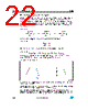
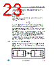
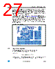
23 / 52 page  LED5000 Application notes - buck conversion Doc ID 023951 Rev 1 23/51 the external power components and the compensation network are selected, a direct measurement to determine TRISE, TFALL (see Equation 24) is necessary to certify the achieved dimming performance. 5.9 Component selection 5.9.1 Sensing resistor In closed loop operation the LED5000 feedback pin voltage is 200 mV, so the sensing resistor calculation is expressed as: Equation 26 Since the main loop (see Chapter 5.1) regulates the sensing resistor voltage drop, the average current is regulated into the LEDs. The integration period is at minimum 5*TSW since the system bandwidth can be dimensioned up to fSW/5 at maximum. A system loop based on a peak current mode architecture features consistent advantages in comparison with simpler closed loop regulation schemes like the hysteretic or the constant ON/OFF control. The system performs the output current regulation over a period which is at least five times longer than the switching frequency. The output current regulation neglects the ripple current contribution and its reliance on external parameters like input voltage and output voltage variations (line transient and LED forward voltage spread). This performance can not be achieved with simpler regulation loops like hysteretic control. For the same reason, the switching frequency is constant over the application conditions, that helps to tune the EMI filtering and to guarantee the maximum LED current ripple specification in the application range. This performance cannot be achieved using constant ON/OFF time architectures. 5.9.2 Inductor and output capacitor selection The output capacitor filters the inductor current ripple that, given the application condition, depends on the inductor value. As a consequence the LED current ripple, that is the main specification for a switching current source, depends on the inductor and output capacitor selection. Figure 16. Equivalent circuit R S 200 mV I LED --------------------- = DCR DCR DCR DCR COUT COUT Rs Rs VIN VIN LL ESR ESR Rd1 Rd1 VIN VIN LL ESR ESR Dled1 Dled1 D D COUT COUT D D Rs Rs Rdn Rdn Dledn Dledn AM13500v1 |
|
链接网址 |
| ALLDATASHEET是否为您带来帮助? [ DONATE ] |
关于 Alldatasheet | 广告服务 | 联系我们 | 隐私政策 | 数据表链接 | 链接交换 | 制造商名单 All Rights Reserved©Alldatasheet.com |
| Russian : Alldatasheetru.com | Korean : Alldatasheet.co.kr | Spanish : Alldatasheet.es | French : Alldatasheet.fr | Italian : Alldatasheetit.com Portuguese : Alldatasheetpt.com | Polish : Alldatasheet.pl | Vietnamese : Alldatasheet.vn Indian : Alldatasheet.in | Mexican : Alldatasheet.com.mx | British : Alldatasheet.co.uk | New Zealand : Alldatasheet.co.nz |
|
Family Site : ic2ic.com |
icmetro.com |
 Chinese ▼
 English
 Chinese
 German
 Japanese
 Russian
 Korean
 Spanish
 French
 Italian
 Portuguese
 Polish
 Vietnamese
 Indian
 Mexican
 British
 New Zealand