|
数据搜索系统,热门电子元器件搜索 |
|
|
数据搜索系统,热门电子元器件搜索 |
|
LED5000 数据表(PDF) 27 Page - STMicroelectronics |
|
|
|||||||||||||||||||||||||||||
LED5000 数据表(HTML) 27 Page - STMicroelectronics |
|
|
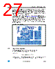
27 / 52 page  LED5000 Application notes - buck conversion Doc ID 023951 Rev 1 27/51 The input and output loops are minimized to avoid radiation and high frequency resonance problems. The feedback pin to the sensing resistor path must be designed as short as possible to avoid pick-up noise. Another important issue is the ground plane of the board. Since the package has an exposed pad, it is very important to connect it to an extended ground plane in order to reduce the thermal resistance junction-to-ambient and increase the noise immunity during the switching operation. In addition, to increase the design noise immunity, different signal and power grounds should be designed in the layout (see Chapter 5.13: Application circuit). The signal ground serves the small signal components, the device analog ground pin, the exposed pad and a small filtering capacitor connected to the VCC pin. The power ground serves the device ground pin and the input filter. The different grounds are connected underneath the output capacitor. Neglecting the current ripple contribution, the current flowing through this component is constant during the switching activity and so this is the cleanest ground point of the buck application circuit. Figure 17. Layout example 5.11 Thermal considerations The dissipated power of the device is tied to three different sources: ● Conduction losses due to the RDSON, which are equal to: Equation 37 Where D is the duty cycle of the application. Note that the duty cycle is theoretically given by the ratio between VOUT (nLED∗VLED + 200 mV) and VIN, but in practice it is substantially AM13501v1 P ON R RDSON_HS I OUT () ⋅ 2 D ⋅ = |
|
链接网址 |
| ALLDATASHEET是否为您带来帮助? [ DONATE ] |
关于 Alldatasheet | 广告服务 | 联系我们 | 隐私政策 | 数据表链接 | 链接交换 | 制造商名单 All Rights Reserved©Alldatasheet.com |
| Russian : Alldatasheetru.com | Korean : Alldatasheet.co.kr | Spanish : Alldatasheet.es | French : Alldatasheet.fr | Italian : Alldatasheetit.com Portuguese : Alldatasheetpt.com | Polish : Alldatasheet.pl | Vietnamese : Alldatasheet.vn Indian : Alldatasheet.in | Mexican : Alldatasheet.com.mx | British : Alldatasheet.co.uk | New Zealand : Alldatasheet.co.nz |
|
Family Site : ic2ic.com |
icmetro.com |
 Chinese ▼
 English
 Chinese
 German
 Japanese
 Russian
 Korean
 Spanish
 French
 Italian
 Portuguese
 Polish
 Vietnamese
 Indian
 Mexican
 British
 New Zealand