|
数据搜索系统,热门电子元器件搜索 |
|
|
数据搜索系统,热门电子元器件搜索 |
|
ICS570B 数据表(PDF) 2 Page - Integrated Circuit Systems |
|
|
|||||||||||||||||||||||||||||
ICS570B 数据表(HTML) 2 Page - Integrated Circuit Systems |
|
|
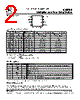
2 / 6 page  ICS570B Multiplier and Zero Delay Buffer MDS 570B A 2 Revision 053001 Integrated Circuit Systems, Inc . • 525 Race Street • San Jose • CA • 95126 • (408)295-9800tel • www.icst.com PRELIMINARY INFORMATION Pin Assignment Number Name Type Description 1 S1 I Select 1 for output clock. Connect to GND, VDD, or float per decoding table above. 2 VDD P Connect to +3.3V. 3 GND P Connect to ground. 4 ICLK CI Reference clock input. 5 FBIN CI Feedback clock input. 6 S0 I Select 0 for output clock. Connect to GND, VDD, or float per decoding table above. 7 CLK O Clock output per table above. 8 CLK/2 O Clock output per table above. Low skew divide by two of pin 7 clock. Pin Descriptions Key: CI = clock input, I = input, O = output, P = power supply connection Clock Multiplier Decoding Table (Multiplies input clock by shown amount) 0 = connect directly to ground. M = leave unconnected (self-biases to VDD/2). 1 = connect directly to VDD. *Input range with CLK feedback is double that for CLK/2. FBIN from CLK FBIN from CLK FBIN from CLK/2 FBIN from CLK/2 25°C ICLK Input Range 85°C ICLK Input Range S1 S0 CLK CLK/2 CLK CLK/2 FB from CLK/2 * FB from CLK/2 * #1 #6 pin # 7 pin # 8 pin # 7 pin # 8 (3.3V, MHz) (3.3V, MHz) 0 0 Power Down and Tri-State Power Down and Tri-State Power Down and Tri-State Power Down and Tri-State - - 0 M x3 x1.5 x6 x3 2.5 to 25 3 to 25 0 1 x4 x2 x8 x4 2.5 to 19 2.5 to 19 M 0 x8 x4 x16 x8 2.5 to 9.5 2.5 to 9.5 M M x6 x3 x12 x6 2.5 to 12.5 2.5 to 12.5 M 1 x10 x5 x20 x10 2.5 to 7.5 2.5 to 7.5 1 0 x1 ÷2 x2 x1 5 to 75 8 to 75 1 M x16 x8 x32 x16 2.5 to 5 2.5 to 5 1 1 x2 x1 x4 x2 2.5 to 37.5 4.5 to 37.5 1 8 2 3 4 7 6 5 S1 GND CLK VDD FBIN 8 pin 150 mil SOIC ICLK CLK/2 S0 External Components The ICS570B requires a 0.01 µF decoupling capacitor to be connected between VDD and GND. It must be connected close to the ICS570B to minimize lead inductance. No external power supply filtering is required for this device. A 27 Ω series terminating resistor can be used next to each output pin. |
|
|
链接网址 |
| ALLDATASHEET是否为您带来帮助? [ DONATE ] |
关于 Alldatasheet | 广告服务 | 联系我们 | 隐私政策 | 数据表链接 | 链接交换 | 制造商名单 All Rights Reserved©Alldatasheet.com |
| Russian : Alldatasheetru.com | Korean : Alldatasheet.co.kr | Spanish : Alldatasheet.es | French : Alldatasheet.fr | Italian : Alldatasheetit.com Portuguese : Alldatasheetpt.com | Polish : Alldatasheet.pl | Vietnamese : Alldatasheet.vn Indian : Alldatasheet.in | Mexican : Alldatasheet.com.mx | British : Alldatasheet.co.uk | New Zealand : Alldatasheet.co.nz |
|
Family Site : ic2ic.com |
icmetro.com |
 Chinese ▼
 English
 Chinese
 German
 Japanese
 Russian
 Korean
 Spanish
 French
 Italian
 Portuguese
 Polish
 Vietnamese
 Indian
 Mexican
 British
 New Zealand