|
数据搜索系统,热门电子元器件搜索 |
|
|
数据搜索系统,热门电子元器件搜索 |
|
ICS570B 数据表(PDF) 1 Page - Integrated Circuit Systems |
|
|
|||||||||||||||||||||||||||||
ICS570B 数据表(HTML) 1 Page - Integrated Circuit Systems |
|
|
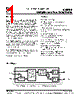
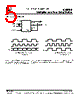
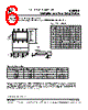
1 / 6 page  ICS570B Multiplier and Zero Delay Buffer MDS 570B A 1 Revision 053001 Integrated Circuit Systems, Inc . • 525 Race Street • San Jose • CA • 95126 • (408)295-9800tel • www.icst.com PRELIMINARY INFORMATION • Packaged in 8 pin SOIC. • Pin-for-pin replacement and upgrade to ICS570/ICS570A • Functional equivalent to AV9170 (not a pin- for-pin replacement). • Low input to output skew of 300 ps max (>60 MHz outputs). • Low skew (100 ps) outputs. • Ability to choose between 14 different multipliers from 0.5X to 32X. • Input clock frequency up to 150 MHz at 3.3V. • Can recover degraded input clock duty cycle. • Output clock duty cycle of 45/55. • Power Down and Tri-State Mode. • Full CMOS clock swings with 25mA drive capability at TTL levels. • Advanced, low power CMOS process. • Operating voltage of 3.3 V (±5%). • Industrial temperature version available The ICS570B is a high performance Zero Delay Buffer (ZDB) which integrates ICS’ proprietary analog/digital Phase Locked Loop (PLL) techniques. The ICS570B, part of ICS’ ClockBlocks™ family, was designed as a performance upgrade to meet today’s higher speed and lower voltage requirements. The zero delay feature means that the rising edge of the input clock aligns with the rising edges of both outputs, giving the appearance of no delay through the device. There are two outputs on the chip, one being a low-skew divide by two of the other. The device incorporates an all-chip power down/tri-state mode that stops the internal PLL and puts both outputs into a high impedance state. The ICS570B is ideal for synchronizing outputs in a large variety of systems, from personal computers to data communications to graphics/video. By allowing off-chip feedback paths, the device can eliminate the delay through other devices. The ICS570B was done to improve input to output jitter from the original ICS570M and ICS570A verisons, and is recommended for all new 3.3 V only designs. For 5V applications, use the ICS570A. Block Diagram Description Features divide by N Phase Detector, Charge Pump, and Loop Filter Voltage Controlled Oscillator CLK Output Buffer ICLK CLK/2 Output Buffer FBIN ÷2 S1, S0 2 External feedback can come from CLK or CLK/2 (see table on page 2). |
类似零件编号 - ICS570B |
|
类似说明 - ICS570B |
|
|
|
链接网址 |
| ALLDATASHEET是否为您带来帮助? [ DONATE ] |
关于 Alldatasheet | 广告服务 | 联系我们 | 隐私政策 | 数据表链接 | 链接交换 | 制造商名单 All Rights Reserved©Alldatasheet.com |
| Russian : Alldatasheetru.com | Korean : Alldatasheet.co.kr | Spanish : Alldatasheet.es | French : Alldatasheet.fr | Italian : Alldatasheetit.com Portuguese : Alldatasheetpt.com | Polish : Alldatasheet.pl | Vietnamese : Alldatasheet.vn Indian : Alldatasheet.in | Mexican : Alldatasheet.com.mx | British : Alldatasheet.co.uk | New Zealand : Alldatasheet.co.nz |
|
Family Site : ic2ic.com |
icmetro.com |
 Chinese ▼
 English
 Chinese
 German
 Japanese
 Russian
 Korean
 Spanish
 French
 Italian
 Portuguese
 Polish
 Vietnamese
 Indian
 Mexican
 British
 New Zealand