|
数据搜索系统,热门电子元器件搜索 |
|
|
数据搜索系统,热门电子元器件搜索 |
|
AD8555ACP-R2 数据表(PDF) 26 Page - Analog Devices |
|
|
|||||||||||||||||||||||||||||
AD8555ACP-R2 数据表(HTML) 26 Page - Analog Devices |
|
|
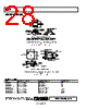
26 / 28 page  AD8555 Rev. 0 | Page 26 of 28 LOAD CAPACITANCE (nF) 100.0 0.1 1.0 10.0 60 50 40 30 20 10 0 RS CL VS = ±2.5V RS = 0 RS = 10 RS = 20 RS = 50 RS = 100 Figure 58. Negative Overshoot Graph vs. CL RF INTERFERENCE All instrumentation amplifiers show dc offset as the result of rectification of high frequency out-of-band signals that appear at their inputs. The circuit in Figure 59 provides good RFI sup- pression without reducing performance within the AD8555 pass band. Resistor R1 and Capacitor C1, and likewise Resistor R2 and Capacitor C2, form a low-pass RC filter that has a −3 dB bandwidth equal to f(−3 dB) = 1/2 π × R1 × C1. It can be seen that R1, R2 and C1, C2 form a bridge circuit whose output appears across the amplifier’s input pins. Any mismatch between C1, C2 unbalances the bridge and reduce the common-mode rejection. Using the component values shown, this filter has a bandwidth of approximately 40 kHz. To preserve common-mode rejection in the AD8555’s pass band, capacitors need to be 5% (silver mica) or better and should be placed as close to its inputs as possible. Resistors should be 1% metal film. Capacitor C3 is needed to maintain common-mode rejection at low frequencies. This introduces a second low-pass network, R1 + R2 and C3 that has a −3 dB frequency equal to 1/(2 π × (R1 + R2)(C3)). This circuit’s −3 dB signal bandwidth is approximately 4 kHz when a C3 value of 0.047 µF is used (see Figure 59). 1 2 3 4 5 6 7 8 AD8555 VDD FILT/DIGOUT DIGIN VNEG VSS VOUT VCLAMP VPOS VPOS VDD VDD VSS VNEG R2 4.02k Ω R1 4.02k Ω C3 0.047 µF C2 1nF C1 1nF Figure 59. RFI Suppression Method SINGLE-SUPPLY DATA ACQUISITION SYSTEM Interfacing bipolar signals to single-supply analog-to-digital converters (ADCs) presents a challenge. The bipolar signal must be mapped into the input range of the ADC. Figure 60 shows how this translation can be achieved. The output offset can be programmed to a desirable level to accommodate the input voltage requirement of the ADC. 1 2 3 4 5 6 7 8 AD8555 VDD FILT/DIGOUT DIGIN VNEG 2 4 AD7476 12 BIT AIN VDD VSS VOUT VCLAMP VPOS VDD VDD SDIGIN 10nF 0 100 Ω 100 Ω 100 Ω 100 Ω Figure 60. A Single-Supply Data Acquisition Circuit Using the AD8555 |
|
|
链接网址 |
| ALLDATASHEET是否为您带来帮助? [ DONATE ] |
关于 Alldatasheet | 广告服务 | 联系我们 | 隐私政策 | 数据表链接 | 链接交换 | 制造商名单 All Rights Reserved©Alldatasheet.com |
| Russian : Alldatasheetru.com | Korean : Alldatasheet.co.kr | Spanish : Alldatasheet.es | French : Alldatasheet.fr | Italian : Alldatasheetit.com Portuguese : Alldatasheetpt.com | Polish : Alldatasheet.pl | Vietnamese : Alldatasheet.vn Indian : Alldatasheet.in | Mexican : Alldatasheet.com.mx | British : Alldatasheet.co.uk | New Zealand : Alldatasheet.co.nz |
|
Family Site : ic2ic.com |
icmetro.com |
 Chinese ▼
 English
 Chinese
 German
 Japanese
 Russian
 Korean
 Spanish
 French
 Italian
 Portuguese
 Polish
 Vietnamese
 Indian
 Mexican
 British
 New Zealand