|
数据搜索系统,热门电子元器件搜索 |
|
|
数据搜索系统,热门电子元器件搜索 |
|
AD8555ACP-R2 数据表(PDF) 27 Page - Analog Devices |
|
|
|||||||||||||||||||||||||||||
AD8555ACP-R2 数据表(HTML) 27 Page - Analog Devices |
|
|
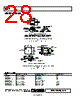
27 / 28 page  AD8555 Rev. 0 | Page 27 of 28 The bridge circuit with a sensitivity of 2 mV/V is excited by a 5 V supply. The full-scale output voltage from the bridge (±10 mV) therefore has a common-mode level of 2.5 V. The AD8555 removes the common-mode component and amplifies the input signal by a factor of 200 (G1 = 4, G2 = 50, Offset = 128). This results in an output signal of ±2.0 V. In order to pre- vent this signal from running into the AD8555’s ground rail, the output offset voltage has to be raised to 2.5 V. This signal is within the input voltage range of the ADC. USING THE AD8555 WITH CAPACITIVE SENSORS Figure 61 shows a crude way of using the AD8555 with capaci- tive sensors. RP1 and RP2 are resistors implementing a potential divider to bias VNEG to VDD/2. Recommended values range from 1 kΩ to 1 MΩ. CS is the capacitive sensor, and RS is a shunt resistor used to prevent leakage currents from integrating on the sensor. The value of RS is application specific. Note that although VNEG is tied to a dc voltage, the only impedance across the capacitive sensor is RS. Therefore, the only way for charge to leak away from CS is through RS, assuming the input bias currents at VPOS and VNEG are negligible. RS CS RP2 RP1 AD8555 VOUT VDD VPOS VNEG Figure 61. Crude Way of Using the AD8555 with Capacitive Sensors The weakness of the circuit in Figure 61 is that the AD8555 input bias current at VPOS flows into RS and creates a differen- tial offset voltage between VPOS and VNEG. This differential offset voltage is amplified by the AD8555. The input bias cur- rent at VNEG, on the other hand, flows into RP1 and create a common-mode shift. This has little impact on VOUT. Despite this weakness, the arrangement in Figure 61 should work if the user wants to minimize the number of components around the sensor, and if the error introduced by the input bias current at VPOS is considered negligible. If greater accuracy is needed, the circuit in Figure 62 is recom- mended. RP1, RP2, and CS are the same as in Figure 61; RP1 and RP2 should be between 1 kΩ to 1 MΩ. RS in Figure 61 has been split into two resistors, RS1 and RS2, in Figure 62. Again, the only way for the capacitive sensor to discharge is through (RS1 + RS2). The input bias current at VPOS flows through RS2 and RP1, and the input bias current at VNEG flows through RS1 and RP1. If RS1 is made equal to RS2 and if the input bias currents are equal, the input bias currents give a common-mode shift at VPOS and VNEG with no differential offset. This common-mode shift is attenuated by the AD8555 common-mode rejection. Further- more, changes in input bias current, e.g., with temperature, manifest as an input common-mode change, also rejected by the AD8555. CS RS2 RP2 RS1 RP1 AD8555 VOUT VDD VPOS VNEG Figure 62. Recommended Way of Using the AD8555 with Capacitive Sensors |
|
|
链接网址 |
| ALLDATASHEET是否为您带来帮助? [ DONATE ] |
关于 Alldatasheet | 广告服务 | 联系我们 | 隐私政策 | 数据表链接 | 链接交换 | 制造商名单 All Rights Reserved©Alldatasheet.com |
| Russian : Alldatasheetru.com | Korean : Alldatasheet.co.kr | Spanish : Alldatasheet.es | French : Alldatasheet.fr | Italian : Alldatasheetit.com Portuguese : Alldatasheetpt.com | Polish : Alldatasheet.pl | Vietnamese : Alldatasheet.vn Indian : Alldatasheet.in | Mexican : Alldatasheet.com.mx | British : Alldatasheet.co.uk | New Zealand : Alldatasheet.co.nz |
|
Family Site : ic2ic.com |
icmetro.com |
 Chinese ▼
 English
 Chinese
 German
 Japanese
 Russian
 Korean
 Spanish
 French
 Italian
 Portuguese
 Polish
 Vietnamese
 Indian
 Mexican
 British
 New Zealand