|
数据搜索系统,热门电子元器件搜索 |
|
|
数据搜索系统,热门电子元器件搜索 |
|
LP2996AMR/NOPB 数据表(PDF) 16 Page - Texas Instruments |
|
|
|
|||||||||||||||||||||||||||||
LP2996AMR/NOPB 数据表(HTML) 16 Page - Texas Instruments |
|
|
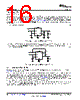
16 / 29 page  R1 LP2996 + + VDDQ VDD VTT VTT PVIN VDDQ GND AVIN VSENSE COUT CIN R2 R1 LP2996 + + VDDQ VDD VTT VTT PVIN VDDQ GND AVIN VSENSE COUT CIN R2 LP2996A SNOSCY7 – JUNE 2014 www.ti.com Typical Application (continued) 8.2.5 Level Shifting If standards other than SSTL-2 are required, such as SSTL-3, it may be necessary to use a different scaling factor than 0.5 times VDDQ for regulating the output voltage. Several options are available to scale the output to any voltage required. One method is to level shift the output by using feedback resistors from VTT to the VSENSE pin. This has been illustrated in Figure 26 and Figure 27. Figure 26 shows how to use two resistors to level shift VTT above the internal reference voltage of VDDQ/2. To calculate the exact voltage at VTT the following equation can be used. VTT = VDDQ/2 ( 1 + R1/R2) (11) Figure 26. Increasing VTT by Level Shifting Conversely, the R2 resistor can be placed between VSENSE and VDDQ to shift the VTT output lower than the internal reference voltage of VDDQ/2. The equations relating VTT and the resistors can be seen below: VTT = VDDQ/2 (1 - R1/R2) (12) Figure 27. Decreasing VTT by Level Shifting 8.2.5.1 Output Capacitor Selection For applications utilizing the LP2996A to terminate SSTL-2 I/O signals the typical application circuit shown in Figure 27 can be implemented. This circuit permits termination in a minimum amount of board space and component count. Capacitor selection can be varied depending on the number of lines terminated and the maximum load transient. However, with motherboards and other applications where VTT is distributed across a long plane it is advisable to use multiple bulk capacitors and addition to high frequency decoupling. Figure 28 shown below depicts an example circuit where 2 bulk output capacitors could be situated at both ends of the VTT plane for optimal placement. Large aluminum electrolytic capacitors are used for their low ESR and low cost. In most PC applications an extensive amount of decoupling is required because of the long interconnects encountered with the DDR-SDRAM DIMMs mounted on modules. As a result bulk aluminum electrolytic capacitors in the range of 1000uF are typically used. 16 Submit Documentation Feedback Copyright © 2014, Texas Instruments Incorporated Product Folder Links: LP2996A |
|
|
链接网址 |
| ALLDATASHEET是否为您带来帮助? [ DONATE ] |
关于 Alldatasheet | 广告服务 | 联系我们 | 隐私政策 | 数据表链接 | 链接交换 | 制造商名单 All Rights Reserved©Alldatasheet.com |
| Russian : Alldatasheetru.com | Korean : Alldatasheet.co.kr | Spanish : Alldatasheet.es | French : Alldatasheet.fr | Italian : Alldatasheetit.com Portuguese : Alldatasheetpt.com | Polish : Alldatasheet.pl | Vietnamese : Alldatasheet.vn Indian : Alldatasheet.in | Mexican : Alldatasheet.com.mx | British : Alldatasheet.co.uk | New Zealand : Alldatasheet.co.nz |
|
Family Site : ic2ic.com |
icmetro.com |
 Chinese ▼
 English
 Chinese
 German
 Japanese
 Russian
 Korean
 Spanish
 French
 Italian
 Portuguese
 Polish
 Vietnamese
 Indian
 Mexican
 British
 New Zealand