|
数据搜索系统,热门电子元器件搜索 |
|
|
数据搜索系统,热门电子元器件搜索 |
|
FT51AL-R 数据表(PDF) 13 Page - Future Technology Devices International Ltd. |
|
|
|||||||||||||||||||||||||||||
FT51AL-R 数据表(HTML) 13 Page - Future Technology Devices International Ltd. |
|
|
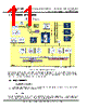
13 / 43 page  Copyright © Future Technology Devices International Limited 13 FT51A Advanced MCU with 8051 Compatible Core IC Datasheet Version 1.5 Doc ument N o.: FT _000877 C learance N o.: FT DI#420 3.2.3 PLL Control The block provides an internally generated 48MHz clock to the system without the need of an external reference clock. This block is trimmed at factory test to 48MHz. During USB transactions the PLL will provide an accurate clock, locked to the incoming USB data rate. 3.2.4 16KB Multi-Time Programmable (MTP) memory 16K bytes of MTP memory are available for firmware programming. Code stored with the MTP memory is copied to the Shadow RAM on power up or an external reset. See section 3.2.6. 3.2.5 8KB Data RAM 8K bytes of data RAM are provided. 3.2.6 16KB Shadow RAM To facilitate fast program memory access, limit any bottlenecks and to allow fast programming times in a debug environment, a shadow RAM exists that the CPU will run from. The Shadow RAM has the following features: The contents of the MTP are copied to the shadow RAM after a system reset – i.e. a POR reset or a pin reset. A single command (register write access) initiates a hard copy of the program memo ry – i.e. the contents of the shadow RAM are copied to the MTP. 3.2.7 Special Function Register The 8051 core has a special function register area (SFR) and is limited to 128 locations. This area facilitates access to IO registers and the USB Full-Speed Device Controller command/data through in- direct addressing method. 3.2.8 IO Registers The FT51A contains approximately 300 IO registers. See Appendix C for a full list of the IO registers. 3.2.9 LDO Regulators The +3.3V LDO regulator generates the +3.3V re ference voltage for driving the USB transceiver cell output buffers. It requires an external decoupling capacitor to be attached to the regulator output pin. The main function of the LDO is to power the USB Transceiver and the Reset Generator Cells rather than to power external logic. However, it can be used to supply external circuitry requiring a +3.3V nominal supply with a maximum current of 50mA. The +1.8V LDO regulator generates the +1.8V supply voltage for internal digital circuits. 3.2.10 BCD Detect Special circuitry inside the FT51A detects when the USB upstream port is connected to a dedicated charging port. When it detects that it is connected to a dedicated charging port, the FT51A can use a DIO or AIO pin to notify a microcontroller or logic on the application board which in turn controls the battery charging circuits. |
|
链接网址 |
| ALLDATASHEET是否为您带来帮助? [ DONATE ] |
关于 Alldatasheet | 广告服务 | 联系我们 | 隐私政策 | 数据表链接 | 链接交换 | 制造商名单 All Rights Reserved©Alldatasheet.com |
| Russian : Alldatasheetru.com | Korean : Alldatasheet.co.kr | Spanish : Alldatasheet.es | French : Alldatasheet.fr | Italian : Alldatasheetit.com Portuguese : Alldatasheetpt.com | Polish : Alldatasheet.pl | Vietnamese : Alldatasheet.vn Indian : Alldatasheet.in | Mexican : Alldatasheet.com.mx | British : Alldatasheet.co.uk | New Zealand : Alldatasheet.co.nz |
|
Family Site : ic2ic.com |
icmetro.com |
 Chinese ▼
 English
 Chinese
 German
 Japanese
 Russian
 Korean
 Spanish
 French
 Italian
 Portuguese
 Polish
 Vietnamese
 Indian
 Mexican
 British
 New Zealand