|
数据搜索系统,热门电子元器件搜索 |
|
|
数据搜索系统,热门电子元器件搜索 |
|
AM6442...ALV 数据表(PDF) 127 Page - Texas Instruments |
|
|
|||||||||||||||||||||||||||||
AM6442...ALV 数据表(HTML) 127 Page - Texas Instruments |
|
|
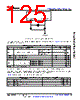
127 / 244 page  7.10.4.1.1.2 Shunt Capacitance The crystal circuit must also be designed such that it does not exceed the maximum shunt capacitance for MCU_OSC0 operating conditions defined in Table 7-17. Shunt capacitance, Cshunt, of the crystal circuit is a combination of crystal shunt capacitance and parasitic contributions. PCB signal traces which connect crystal circuit components to MCU_OSC0 have mutual parasitic capacitance to each other, CPCBXIXO, where the PCB designer should be able to extract mutual parasitic capacitance between these signal traces. The device package also has mutual parasitic capacitance, CXIXO, where this mutual parasitic capacitance value is defined in Table 7-18. PCB routing should be designed to minimize mutual capacitance between XI and XO signal traces. This is typically done by keeping signal traces short and not routing them in close proximity. Mutual capacitance can also be minimized by placing a ground trace between these signals when the layout requires them to be routed in close proximity. It is important to minimize the mutual capacitance on the PCB to provide as much margin as possible when selecting a crystal. AM65x_MCU_OSC_SC_06 Device MCU_OSC0_XO MCU_OSC0_XI C PCBXIXO PCB Signal Traces Crystal Circuit Components C XIXO C O Figure 7-20. Shunt Capacitance A crystal should be chosen such that the below equation is satisfied. CO in the equation is the maximum shunt capacitance specified by the crystal manufacturer. Cshunt ≥ CO + CPCBXIXO + CXIXO For example, the equation would be satisfied when the crystal being used is 25 MHz with an ESR = 30 Ω, CPCBXIXO = 0.04 pF, CXIXO = 0.01 pF, and shunt capacitance of the crystal is less than or equal to 6.95 pF. 7.10.4.1.2 MCU_OSC0 LVCMOS Digital Clock Source Figure 7-21 shows the recommended oscillator connections when MCU_OSC0_XI is connected to a 1.8-V LVCMOS square-wave digital clock source. Note A DC steady-state condition is not allowed on MCU_OSC0_XI when the oscillator is powered up. This is not allowed because MCU_OSC0_XI is internally AC coupled to a comparator that may enter a unknown state when DC is applied to the input. Therefore, application software should power down MCU_OSC0 any time MCU_OSC0_XI is not toggling between logic states. www.ti.com AM6442, AM6441, AM6421, AM6412, AM6411 SPRSP56D – JANUARY 2021 – REVISED JULY 2022 Copyright © 2022 Texas Instruments Incorporated Submit Document Feedback 127 Product Folder Links: AM6442 AM6441 AM6421 AM6412 AM6411 |
|
链接网址 |
| ALLDATASHEET是否为您带来帮助? [ DONATE ] |
关于 Alldatasheet | 广告服务 | 联系我们 | 隐私政策 | 数据表链接 | 链接交换 | 制造商名单 All Rights Reserved©Alldatasheet.com |
| Russian : Alldatasheetru.com | Korean : Alldatasheet.co.kr | Spanish : Alldatasheet.es | French : Alldatasheet.fr | Italian : Alldatasheetit.com Portuguese : Alldatasheetpt.com | Polish : Alldatasheet.pl | Vietnamese : Alldatasheet.vn Indian : Alldatasheet.in | Mexican : Alldatasheet.com.mx | British : Alldatasheet.co.uk | New Zealand : Alldatasheet.co.nz |
|
Family Site : ic2ic.com |
icmetro.com |
 Chinese ▼
 English
 Chinese
 German
 Japanese
 Russian
 Korean
 Spanish
 French
 Italian
 Portuguese
 Polish
 Vietnamese
 Indian
 Mexican
 British
 New Zealand