|
数据搜索系统,热门电子元器件搜索 |
|
|
数据搜索系统,热门电子元器件搜索 |
|
P9225-R 数据表(PDF) 6 Page - Renesas Technology Corp |
|
|
|||||||||||||||||||||||||||||
P9225-R 数据表(HTML) 6 Page - Renesas Technology Corp |
|
|
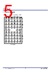
6 / 35 page  P9225-R Datasheet © 2018 Integrated Device Technology, Inc. 6 November 12, 2018 2. Pin Descriptions Table 1. Pin Descriptions Pins Name Type Function A1 COM1 Output Open-drain output used to communicate with the transmitter. Connect a 47nF capacitor from AC1 to COM1. A2 EOC Input Active-HIGH End-of-Charge input pin. When connected to logic HIGH, the device sends an End Power Transfer (i.e., charge complete) packet to the transmitter to terminate power delivery and shuts down. Use a 10kΩ resistor to GND to pull this pin down to logic LOW by default. A3 SCL Input Serial clock line. Open-drain pin. Connect this pin to a 5.1kΩ resistor to VDD18 pin if I2C access by external AP is used. Otherwise, this pin can be left floating. A4 VOSET Input Programming pin for setting the output voltage. Connect this pin to the center tap of the external resistor divider to set the output voltage. For more information, refer to section 8.2 for different output voltage settings. A5 RPPG Input Received Power Packet Gain (RPPG) calibration pin for foreign object detection (FOD) tuning. Connect this pin to the center tap of the external resistor divider to set the gain of the FOD. The FOD is disabled by connecting RPPG and RPPO to GND. Do not leave this pin floating. A6 COM2 Output Open-drain output used to communicate with the transmitter. Connect a 47nF capacitor from AC2 to COM2. B1 COMA Output Open-drain output used to communicate with the transmitter. Connect a 47nF capacitor from AC2 to COMA. If PMA mode is not used, this pin can be left floating. B2 RSV0 – Reserved pin. B3 SDA Input/Output Serial data line. Open-drain pin. Connect this pin to a 5.1kΩ resistor to VDD18 pin if I2C access by external AP is used. Otherwise, this pin can be left floating. B4 ILIM Input Programmable over-current limit pin. Connect this pin to the center tap of a resistor divider to set the current limit. For more information about the current limit function, see section 8.5. B5 EN ���� Input Active-LOWenablepin.PullingthispintologicHIGHforcesthedeviceintoShutDownMode. When connected to logic LOW, the device is enabled. Do not leave this pin floating. B6 COMB Output Open-drain output used to communicate with the transmitter. Connect a 47nF capacitor from AC2 to COMB. If PMA mode is not used, this pin can be left floating. C1, C6, J1, J2, J3, J4, J5, J6 GND GND Ground. C2 SINK Output Open-drain output for controlling the rectifier clamp. Short this pin to the VRECT pin. C3 INT ���� Output Interruptflagpin.Thisisanopen-drainoutputthatsignalsfaultinterrupts.ItispulledLOWifany of these faults exist: an over-voltage is detected, an over-current condition is detected, the die temperature exceeds 140°C, or an external over-temperature condition is detected on the TS pin. It is also asserted LOW when EN is HIGH. Connect to VDD18 through a 10kΩ resistor. See section 8.6 for additional conditions affecting the interrupt flag. C4 RPPO Input Received Power Packet Offset (RPPO) calibration pin for FOD tuning. Connect this pin to the center tap of the external resistor divider to set the offset of the FOD. The FOD is disabled by connecting RPPG and RPPO to GND. Do not leave this pin floating. C5 RSV4 Input Reserved. This pin must be connected to a 10kΩ resistor to the VDD18 pin. |
|
链接网址 |
| ALLDATASHEET是否为您带来帮助? [ DONATE ] |
关于 Alldatasheet | 广告服务 | 联系我们 | 隐私政策 | 数据表链接 | 链接交换 | 制造商名单 All Rights Reserved©Alldatasheet.com |
| Russian : Alldatasheetru.com | Korean : Alldatasheet.co.kr | Spanish : Alldatasheet.es | French : Alldatasheet.fr | Italian : Alldatasheetit.com Portuguese : Alldatasheetpt.com | Polish : Alldatasheet.pl | Vietnamese : Alldatasheet.vn Indian : Alldatasheet.in | Mexican : Alldatasheet.com.mx | British : Alldatasheet.co.uk | New Zealand : Alldatasheet.co.nz |
|
Family Site : ic2ic.com |
icmetro.com |
 Chinese ▼
 English
 Chinese
 German
 Japanese
 Russian
 Korean
 Spanish
 French
 Italian
 Portuguese
 Polish
 Vietnamese
 Indian
 Mexican
 British
 New Zealand